

100mV RF to Digital
 Phil Pilgrim (PhiPi)
Posts: 23,514
Phil Pilgrim (PhiPi)
Posts: 23,514
I'm working on a project to control the VFO of a 40m MFJ Cub QRP transceiver, using a Prop in a digital PLL feedback loop. The VFO is a VCO controlled, nominally, by a potentiometer. By tapping the center pole of the pot and applying a voltage from an op amp fed with a DUTY-mode counter output, the Prop can control the transceiver's transmit and receive frequency. The challenge I've faced is getting the meager 100mV P-P sine-wave output from the VCO converted to a reliable digital feedback signal -- with no false edges -- that the Prop can read to determine the actual VCO frequency and phase. Here's the circuit that I'm using at the moment:

The J310 JFET provides a high-impedance input from the VCO with minimal loading feedback that could distort the VCO's waveform. The common-source output feeds a CMOS inverter configured as a high-gain amplifier (due to the 10M feedback resistor). The output of the amplifier is low-pass filtered and fed into an inverting buffer stage. The output of that stage feeds back through a 6pF cap to the input of the first stage to provide a little bit of hysteresis -- hopefully to reduce the effects of oscillation.
The circuit seems to work fine, but I wonder if there's a simpler (read "cheaper") way to accomplish the same end. A high-speed JFET-input op amp and a few passives could do the job, but for a lot more money. Feeding the VCO output directly to a sigma-delta-style Prop input distorts the VCO's waveform too much to use for transmitting, so that's out. Any ideas? Beau?
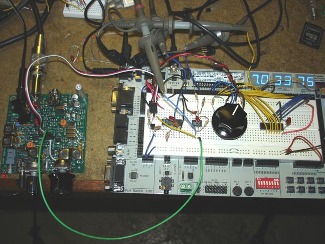
BTW, here's a photo of my test bed for the frequency controller: The PPDB has proven to be the perfect platform for testing the circuitry and DPLL code. The knob controls a contact-closure quadrature encoder for changing the target frequency, and the LED display shows the actual VCO frequency (subtracted from the 12 MHZ IF). Since the VCO ranges from 4.94 MHz to 5.00 MHz (7.06 MHz to 7.00 MHz RF input range), I found it necessary to change the Prop's 5MHz crystal to 4.9152 MHz (one that I had in stock). This prevents the long-term jitter from the Prop counter's PLL near the former 5 MHz clock frequency from causing similar jitter in the transceiver's VCO.

Thanks,
-Phil, AD7YF
The J310 JFET provides a high-impedance input from the VCO with minimal loading feedback that could distort the VCO's waveform. The common-source output feeds a CMOS inverter configured as a high-gain amplifier (due to the 10M feedback resistor). The output of the amplifier is low-pass filtered and fed into an inverting buffer stage. The output of that stage feeds back through a 6pF cap to the input of the first stage to provide a little bit of hysteresis -- hopefully to reduce the effects of oscillation.
The circuit seems to work fine, but I wonder if there's a simpler (read "cheaper") way to accomplish the same end. A high-speed JFET-input op amp and a few passives could do the job, but for a lot more money. Feeding the VCO output directly to a sigma-delta-style Prop input distorts the VCO's waveform too much to use for transmitting, so that's out. Any ideas? Beau?
BTW, here's a photo of my test bed for the frequency controller: The PPDB has proven to be the perfect platform for testing the circuitry and DPLL code. The knob controls a contact-closure quadrature encoder for changing the target frequency, and the LED display shows the actual VCO frequency (subtracted from the 12 MHZ IF). Since the VCO ranges from 4.94 MHz to 5.00 MHz (7.06 MHz to 7.00 MHz RF input range), I found it necessary to change the Prop's 5MHz crystal to 4.9152 MHz (one that I had in stock). This prevents the long-term jitter from the Prop counter's PLL near the former 5 MHz clock frequency from causing similar jitter in the transceiver's VCO.
Thanks,
-Phil, AD7YF
648 x 486 - 81K

620 x 240 - 3K
Comments
What if you created a false ground reference that was close to the I/O threshold and lifted the current ground reference? ... I assume the the 100mV is at the 1k 220pF junction?
You could also try increasing the 1k value off of the J-fet.
...let me sleep on it.
I've done that when the signal level is much higher, but 100 mV is not adequate to guarantee straddling the logic threshold when the bias is fixed, let alone getting a 50% duty cycle, which I need for the phase detection.
Both the JFET gate and the source. Since it's a follower, it doesn't amplify the voltage; it just isolates the VCO from what comes after.
No, the FET seems to do a good job of isolating the VCO from the rest of the circuit.
BTW, I tried a common-source JFET circuit to get some voltage gain. The Spice simulation showed a lot more gain than my circuit did, though.
-Phil
The first one with the LC is a typical re-gen configuration. The second one is a derivative that should accept your 100mV signal just fine.
The basic idea is the same for both. The 100k and 100nF cap automatically bias and track the transistor threshold across the B-E junctions. In the case of the LC it becomes part of the bias loop. In the case of the RF it's 'injected' into the bias loop.
In a way this circuit is similar to connecting the output of your inverter to the input ... which forms a bias loop for that circuit.
Which circuit is better? It's hard to say, but I think that the propagation delay and the high side driving of the inverters might be detrimental. With the bipolar transistors the propagation will be much lower.
-Phil
In the meantime, Ken has tasked me with a project that has priority, so it may be awhile before I can get back to this -- unless I get stuck on Ken's project and need a break.
-Phil
I'm trying out several different ones:
TS3011: 8ns, push-pull, $1.341/M
TS3021: 38ns, push-pull, $0.558/M
TLV3501A: 4.5ns, push-pull, $1.320/M
MCP6566: 56ns, open-drain, $0.39/M
Speed seems to be the biggest determinant of price. As long as the delay times are symmetrical, any of these -- including, hopefully, the slowest ones -- should work at 5 MHz, which is my frequency of interest. But I'll test them all and post scope traces of the results.
-Phil
I've seen circuit A touted for zero-crossing detection, but I'm not sure I trust it, even for comparators with rail-to-rail inputs. Depending on the input offset value, a common-mode input below ground may still register positive. As long as the input's DC component is within the comparator's common-mode range, I'm more inclined to go with B.
-Phil
I'll be interested to hear what you find. Easy enough to swap the R and the C! The big issue with these chips is tight layout, bypassing, and shielding from parasitic feedback.
Here is another amplifier circuit that is good for high frequency performance. The bias in this case comes from matched transistors, where the bias in R3 is mirrored in R2. The signal is input at the emitter, low impedance, so it avoids the Early effect. The gain on paper is R2/R1. I see from the simplified schematic of the LMV7219 that it uses that configuration as a the second stage, after the PNP input, with R2 replaced by a current source.
That eliminates the TLV3501, LMV7219, and TS3011.
The TS3021 works okay, but the output is nowhere close to a 50% duty cycle. That leaves the slowest (and cheapest) contender: the MCP6566. This is the only one that has an open-collector output, and it's rated to a maximum toggle frequency of 4 MHz at Vdd = 5.5V. (I need 5 MHz at 3.3V.) Nonethless, I do get a 50% duty cycle output from it. What's puzzling, though, is that to get any respectable rise time from it, I need to use a 680-ohm (or smaller) pullup resistor. Otherwise, the output looks like it's driving a huge capacitive load. (I may try adding a cascoded transistor to the output to see if that helps.) Anyway, here's what the input and its spectrum look like with the comparator powered down:
Here's what they look like -- along with the comparator output -- with the comparator powered up:
As you can see, there is quite a bit of noise fed back to the oscillator circuit, which is probably going to be unacceptable. This may entail a buffer stage ahead of the comparator to isolate the oscillator from the noise. But then we're getting back to too many components again.
'Not sure what to try next...
-Phil
Sorry to sidetrack you here..
Here's a scope trace of the input signal and counter feedback:
Virtually nothing got fed back to the oscillator either. The spectrum analyzer trace, sampled at the oscillator output, is clean, except for a sharp peak at 5 MHz.
But ... the duty cycle is not 50%. This is because the Propeller's input threshold is not exactly Vdd/2. The way to fix this is to have the counter feedback drive a non-inverting op-amp integrator whose "ground" reference is Vdd/2. The output from the integrator would then be used to bias the counter input via the 1M resistor.
More to come...
-Phil
P.S. Don: The scope, which I've had for years, is a Tektronix TDS 3014. The recently-acquired spectrum analyzer is a Rigol DSA 815 TG. I'm very happy with both.
My experimental setup was not the best, that's for certain. I'd have to do a custom PCB to improve matters, though -- or maybe dead-bug style on some bare copper-clad (ugh). As to the FET, no, I tried to do without it.
I'm encouraged, though, by the simpler circuit above. I think that, by adding an integrator, I might end up where I want to be.
-Phil
No particular reason for the component values I used. 'Just grabbed the closest parts atop my messy (again) bench.
Here are the scope traces:
I think I'm happy now and have everything I need to start laying out a PCB for the transceiver.
-Phil
I noticed that the frequency the Prop was measuring for its feedback signal was higher than that of the spectrum analyzer for the oscillator. Sure enough: runts! Hysteresis is going to inject noise into the oscillator, though. Maybe I should just filter the counter output, feed it back into the Prop, and use that as my frequency input. Hmmm.
-Phil
-Phil
Layout doesn't look so critical, except for the node closest to the Prop input pin. Should that node be close to the oscillator circuit? It might benefit from the follower to make a signal that can be delivered over a length of coax. I see that the transceiver does already have a follower, Q4, that samples the oscillator output and delivers it to the transmitter section.
The topic of using external comparators in a sigma-delta loop has come up from time to time, as a way to avoid the ground bounce and threshold errors of the prop itself. Your experiment points out the difficulty of doing so. Layout counts!
Yes, that's where I'm tapping the oscillator signal from. The top of the pot that controls the amplitude going to the transmitter is a convenient place to solder a wire -- or even a piece of coax, should that be necessary.
I may replace the polystyrene caps in the oscillator with ones that have a lower profile. With a PLL, their temperature stability is no longer needed, and their high-profile loopy leads are going to make a nice antenna for picking up noise from the Prop.
Overall, my plan is this: remove the two control pots from the font of the transceiver PCB. These will be replaced by a vertically-oriented PCB of my own, substituting encoders for the controls. The board will also have a six-digit, 7-segment frequency display. The encoders have built-in pushbuttons, which can be used to select alternate functions: step size for frequency and a narrow-band audio filter for the volume. I'll have to reamplify the audio, though, since it will be passing through the Prop.
-Phil