The QuickStart Pin Finder
So I'm way more of hardware guy than software. Therefore making circuits easier to "wire-up" is always on my mind.
However, in this case I was beat-to-the-punch by a good friend who came up with this idea...
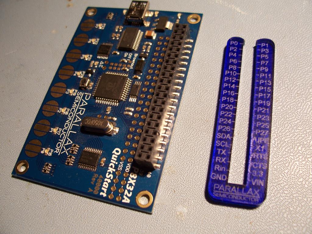
It's called the "QuickStart Pin Finder" -
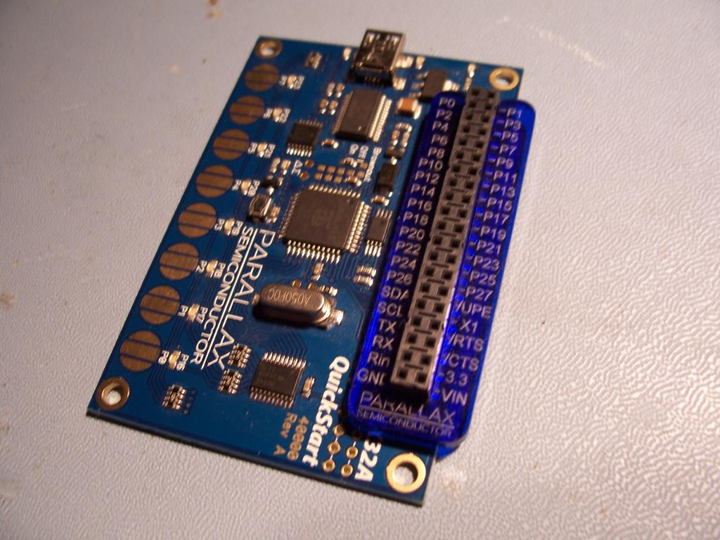
It slides over and clamps onto the female header. When you're done bread-boarding the circuit, you simply spread the "tangs" and slide it off.
It's cheap...er, inexpensive! And quite useful perhaps.

It "snaps" on, so it doesn't fall off (even if upside-down)...

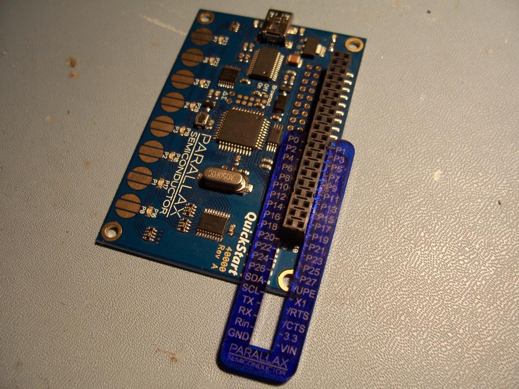
...and then you just spread the "pinchers", and it slides right off (even after you've put jumper wires into the header).

So what do you think, should we make these available? Do they enhance the QS's usability factor?
-MattG
However, in this case I was beat-to-the-punch by a good friend who came up with this idea...
It's called the "QuickStart Pin Finder" -
It slides over and clamps onto the female header. When you're done bread-boarding the circuit, you simply spread the "tangs" and slide it off.
It's cheap...er, inexpensive! And quite useful perhaps.

It "snaps" on, so it doesn't fall off (even if upside-down)...

...and then you just spread the "pinchers", and it slides right off (even after you've put jumper wires into the header).

So what do you think, should we make these available? Do they enhance the QS's usability factor?
-MattG


Comments
'Sorry for not getting back to you sooner about the samples Ken brought me. I like them. They have two advantages over labels that stick to the sides of the connector:
2. When stacked two-high (see photo), they're almost level with the top of the connector, eliminating any parallax errors. (This is also an advantage over printing the pin IDs directly on the board.)
They do seem a bit bulky, but the advantages far outweigh the bulkiness. Initially, I thought, "Why not enclose both ends?" But then I realized that with one end open, it can be removed without disturbing any wires that might be plugged into the connector.
In summary, I think you have a winner!
-Phil
Phil's stickers are a great option.
This is another great solution.
BTW, was there a reason you did the U-end on the side with the extra +V/Gnd taps, and not the other side? I've got soldered-on headers there on mine, and they'll obstruct the plastic, even if the piece is elevated.
-- Gordon
It can, but if it does then it will be "propped up" onto the larger components on that side, which kinda signifies to the user that it's not on "the right way".
Right you are! However, it does have enough room to use two sets of the power pins (not all four, until you remove it).
If it were reversed (top for bottom - clamp side "up", is that better? All power pins would be available, but it would not "sit flat" on the QS board. Which is worse/better?
-MattG
Could you also do another run of the Inventor's Wands" ? I traveled all the way the Makerfaire NY to get one, but, alas UPS lost them.
Jim
Will the laser cutter files that Parallax uses work on the Prusa?
jim
As a starting point, they sure will. They also might work on a laser cutter, but I'm not the expert here.
UPS found them, and I got the whole box on my shelf right now. We never did turn it into a product. I thought it would be a good "buy $75 worth of stuff and get a free Inventor's Wand" perk.
What do you all think? Should we make it available for purchase as well (not you Pub, you'll get a complimentary one for bringing it back to my finite little mind).
Heck, it's got the resistor color code, drill and tap sizes, and Isaac's 3 laws of robotics emblazened right where you need 'em.
-MattG
I can post the .dxf's if that'll work for ya?
-MattG
(CLICK TO ENLARGE)
But that just goes to show you how the sharing of ideas can lead to product improvement before we ever begin the production run of the actual product. Feedback from customers like yourselves has helped us improve on several of our product offerings.
When Matt first gave me the prototype units above I loved them. But what they reminded me of is something called a Wrap-ID. Some of you veteran engineers/hackers will know what I am talking about. For those that don't, back in the late 80s/early 90s wire-wrapping was still a common way to prototype microcontroller and CPU-based projects due to the high cost of PCB production back then. The problem is that when you flip the breadboard over to wrap the pins everything is upside down, so the pins are sort of backwards. These Wrap-IDs (shown below, yes I still have some) made it easy to see the correct pins numbers from the bottom side of the board while wrapping dozens of pin-to-pin connections. The blank space allowed you to use a sharpie and write in the IC name.
(CLICK TO ENLARGE)
Here's a board that was wire-wrapped using Wrap-ID and has a Z80 CPU, 8255PIA and numerous support chips (circa 1991). You can't see the stuff underneath in the photo, but maybe can appreciate how much these guys helped on a board like this which was wired upside down. Again, I think the QuickStart Pin Finder will be just as useful for those experimenting with their QuickStart Boards. I know I will be using it on mine.
OBC
I'm sure a paper version would be easy to make. I tried that with the Wrap-IDs because I didn't have enough. Mine weren't nearly as easy to make (all those holes) or read. A paper version of the QS Pin Finder wouldn't stay put on the board if moving it around I would think, but may get you by in a pinch.
Please do post the dxf, I'd like to make one.
I think "cavelamb" (I'm not sure if I got his name right. Has a paper version he's shared on the forum.
As for the plastic version goes, how about cutting a notch in one end of the Inverter Wand and make a two in one device?
I'm personally a fan of stickers for the QuickStart. Like Gordon, I populate my Vdd and Vss holes. I usually have pins in holes 39 and 40 which I use to plug in a battery pack, so this particular Pin Finder wouldn't be very useful to me.
We actually talked about a sticker instead. When using stickers they leave a gummy residue which is hard to remove in the confined space if you should decide later to solder to the pads below the connector. Personally I was againt the sticker idea and in favor of Matt's plastic unit, mainly for that reason.
So, you can't see it yet because I'm home and don't happen to have a spare Laser cutter in my garage, but...
...I've made modifications - based on your input - to the Pin Finder:
The ends are reversed, so the clippy part is now near the Vdd/Vss unpopulated header area. It's been trimmed such that you can access all holes on the header, and the clips are still able to do their job. The Fat End is now at the top and is the direction in which you remove the Pin Finder from the Quick Start.
Getting closer to the "best of all worlds"...Pics to come Monday :thumb:
-MattG
I wasn't suggesting putting labels directly on the PCB.
I was thinking of something like Phil's nice labels for the QuickStart header. My version of a sticker set (made before Phil sent me a set of his nice labels) is on the right which I made using a Brother label maker.
Besides adding labels and headers on the Vdd/Vss holes, I also add a pair of male headers on Vin and Vss holes so I can plug in a battery pack.
I'm not suggesting the Pin Finder is a bad idea, I just personally like stickers on my (many) QuickStart boards. I often wonder how people get by without stickers on their QuickStart boards.
dfx can work, that will get me going!
PDF attached.
quickstart_clip.pdf
Cool! What material is it made from? 'Looks like laser-engraved MakerBot output.
-Phil