Work in Progress: Networked ATV robot using Spinneret
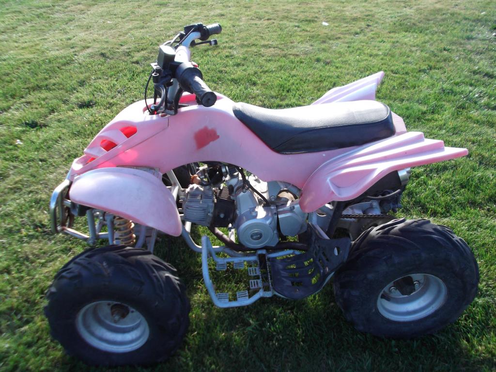
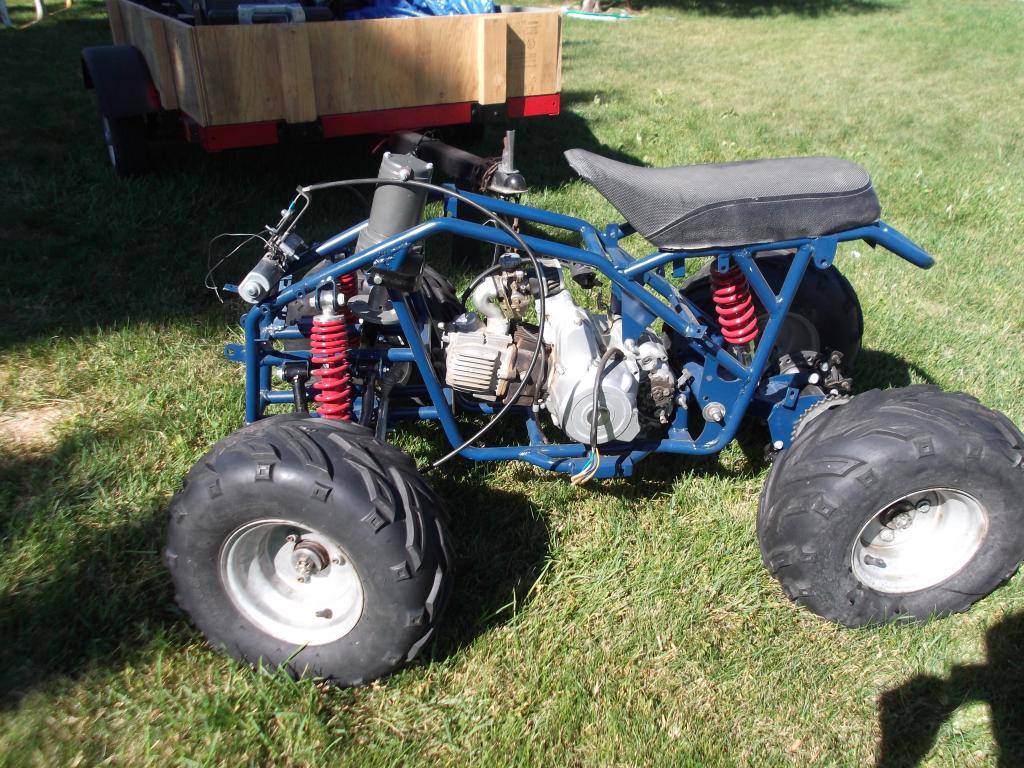
Since giving up on my 5 horse robot I couldn't help myself, I wanted to get something to work. So when I found a 110cc ATV on Craigslist for $100 I couldn't help myself! It's taken 2 months but I've finally gotten some of the biggest challenges out of the way: I gave it brakes and steering. I still have to get the motors controlled by the Propeller, but after what I went through to figure out how to setup motors in the first place, the electronics are the easy part.
I still have a long way to go to setup all the electronics, especially since I've invested enough now that my budget is tight until I find a job, but for now here are the goals:
The robot and the controller will use a Spinneret to communicate, using Open-Mesh routers that will allow for an expansion of domain using multiple nodes repeating the data. (phew---long explanation)
Packets will be consistently sent to ensure the robot is in wireless range. If not, it will be able to backtrack using GPS.
The robot will be able to patrol a perimeter for a security guard.
It will be able to travel to set locations, or be given GPS coordinates and autonomously navigate.
Someday (when I can afford it) it will be able to coordinate with a quadricopter to bounce wireless signals down to it for long range wireless communication.
Potential uses someday:
Security Patrol
Military
Border Patrol
Search & Rescue
Hazardous area surveillance
Sorry for the long explanation, I at least hope you will enjoy following this as I make this thing work! And I look forward to your advice as I move forward so I can avoid costly mistakes (already made a few, guess that means I need you guys!).
Will keep you all posted as I move forward, hope you enjoy the pics!


Comments
Currently I'm working on setting up the electronics so I can begin testing different parts of the robot. Most of my setup however is meant to be temporary, since I intend for the testing to help me determine the best way to set everything up permanently, and also because a lot of what I would like to do will require much more time and more resources than I currently have.
Below is the picture of the motor in charge of my front brakes. Eventually I want it in an enclosure with a relay and capacitors setup to run the motor long enough to apply the brakes if there is a power loss. Also, it will probably later have a microcontroller in it to ensure there is communication to various parts of the robot or it will apply the brakes.
The electronics in the pictures below aren't mounted yet. First I will be getting everything inside setup for controlling the robot, then I will be attaching it temporarily with zip-ties until I get the chance to improve the case how I want, which will include a clear dome over the camera. Then I will create a bracket for the case to be bolted on to. Currently the intent is for the robot to use a Spinneret, a Protoboard, and if I run out of pins for sensors, then possibly the MSP430 chip. But for now, I'm trying to keep things simple.
I have a video below explaining and showing my setup, but I'm going to explain it better here:
Wii classic remote connected to spinneret, sends tcp packet via ethernet to an Open-Mesh router.
The second spinneret receives this packet from a second Open-Mesh router.
The data received is then sent serially from the spinneret to the prop proto board.
The prop proto board (I call it the main board) finds out the position of the steering using the rotations of the motor.
The main board requests data continually from a ADC chip connected to a hall effect sensor I glued inside the motor. When the magnet glued inside passes near, the ADC values decrease.
-I need to mount an effective sensor to zero this system after a reset.