

MCP3208 Delay Based on Vdd and Input Resistance
 Duane Degn
Posts: 10,588
Duane Degn
Posts: 10,588
In the past, I've had trouble measuring voltages with a MCP3208 ADC chip when using a high impedence input source.
In hopes of having more control over the timing of how the Propeller reads from the chip, I'm writting my own driver for the MCP3208.
I think the critical time is the sample period which takes place between the fourth rising clock edge after the start bit and the falling edge of the fifth clock pulse.
I think the time required by the chip to read from the input source is dependent on the chip's supply voltage and the resistance of the input source.
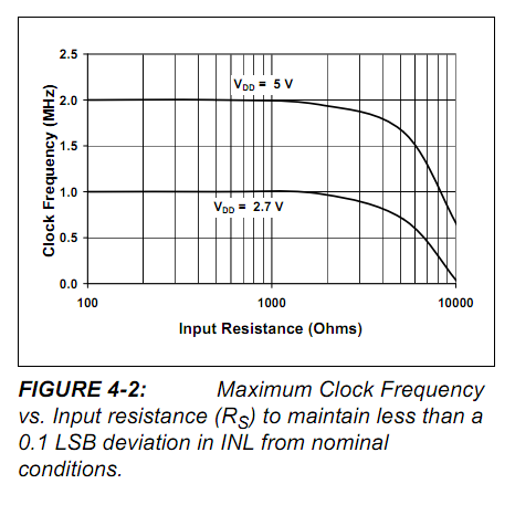
Page 18 of the datasheet has this graph.

I'm hoping someone here is better at curve fitting than I am and can help me come up with an equation to determine the time the driver should pause to allow a good reading from the input. I think there should be a way to describe this graph with an equation using both Vdd of the MCP3208 chip and the input resistance of the voltage to measure. I think it would be safe to assume that Vdd would likely be between 3.3V and 5V.
My plan is to include Vdd and the highest input resistance expected as parameters in an init or start method. Hopefully the appropriate delay can be added that will increase the accuracy of the readings while allowing the maximum read speed for a given set of parameters.
My initial guess is this is a logrithmic relationship. If any of you have suggestions, I'd be glad to hear them.
Thanks,
In hopes of having more control over the timing of how the Propeller reads from the chip, I'm writting my own driver for the MCP3208.
I think the critical time is the sample period which takes place between the fourth rising clock edge after the start bit and the falling edge of the fifth clock pulse.
I think the time required by the chip to read from the input source is dependent on the chip's supply voltage and the resistance of the input source.
Page 18 of the datasheet has this graph.
I'm hoping someone here is better at curve fitting than I am and can help me come up with an equation to determine the time the driver should pause to allow a good reading from the input. I think there should be a way to describe this graph with an equation using both Vdd of the MCP3208 chip and the input resistance of the voltage to measure. I think it would be safe to assume that Vdd would likely be between 3.3V and 5V.
My plan is to include Vdd and the highest input resistance expected as parameters in an init or start method. Hopefully the appropriate delay can be added that will increase the accuracy of the readings while allowing the maximum read speed for a given set of parameters.
My initial guess is this is a logrithmic relationship. If any of you have suggestions, I'd be glad to hear them.
Thanks,
466 x 476 - 44K
Comments
-Phil
The most insidious effect of insufficient sampling time is crosstalk: the signal on one channel affects the reading on the neighboring channels. There is not enough time for the sampling capacitor to swing all the way to the new level. I'd say as a rule of thumb to allow 10 time constants.
(1/e)^10 = 0.000123. Compare that with the resolution of a 12 bit converter. 1/4096=0.000244. So if one channel is a zero volts and the next channel is at full scale, after 10 time constants the sampling capacitor will slew to within 1/2 bit of error. For example, 5V supply, 4000Ω source resistance + 1000Ω switch resistance, 20pF capacitor, time constant 0.1µs. 10 time constants is then 1µS. The '3208 samples for two clock periods (or is it 1.5?), so that corresponds to a frequency between 1 and 2 MHz.
Are you thinking to stretch out the clock pulses during the sampling time? Good idea!
The calculation above falls pretty close to the graph, but I am puzzled by the caption that talks about 0.1 LSB deviation. That it seems to me would take a few more time constants and not much to be gained above the specs.
If the input signals and the ADC sampling are slow, you can hang a capacitor on each input channel. The sampling capacitor grabs a little charge off of that capacitor, each time it samples, and the source resistance has to have time to charge the input capacitor back up before the next sample is taken. It can be made quantitative.
If the signal is fast, then an input capacitor or even a longer sampling window won't be satisfactory. The best solution then is a stable buffer amplifier.
If I gang the inputs between the two MCP's I can exaggerate the behavior ... (see attached image) ... However, this behavior is completely normal for a capacitor charge transfer style ADC. You can minimize this behavior with an external capacitor, but it still will be there to some degree. ... OR you can wait as Tracy suggests by stretching the clock during the sample period. ...Referring to the attached image, although the signal is not as deep when the channels are ganged, it still takes about 200ns for the internal capacitor to fully charge (the impedance is about 400 Ohms in my particular setup with an 18kHz 3.4V Pk-Pk sine wave)
Looking at the flipside of this - if one were to deliberately introduce a low impedance "reference" channel (say 3v3 with decent bypass cap, or hard 0V), which was deliberately scanned just before the (slowly changing) channel of interest, it might be possible to estimate the source impedance of the signal channel, and thereby estimate what kind of sampling rate vs error is possible in advance.
It would only work for a range of input impedance, but if clock _shortening_ of the sampling period worked, perhaps that range could be extended.
This may be a silly question, but why not just buffer the signal to a low impedance and finesse the issue? The drop in performance is due to the input impedance of the internal ADC circuitry (often modelled as a series resistance and a capacitance to ground) which is probably quite variable between devices and not to be relied on. The fact that there is a graph in the datasheet is not a guarantee that all devices perform like this (often graphs are "typical performance").
Driving the input with a low impedance is good practice anyway to reduce noise and capacitive pickup from the digital signals flying about on the same chip.
I also suspect someone using thedriver needs to know the sample rate, its kind of essential to most digital signal processing, so that needs to be configurable directly by the user rather than letting the driver derive it opaquely from other parameters.
I hadn't thought about adding a cap on the input. That's a good idea.
My current project that uses a MCP3208 is to read the voltage on the wiper of a 10K potentiometer used to monitor the position of a DIY servo. As I was testing my code, I used a 5MHz clock frequency so my logic analyzer could catch all the clock pulses.
My original code worked fine at 5MHz with a 10K ohm input but I found I got very different readings when I increased the Prop's clock speed up to 80MHz.
I'm hoping that stretching the one and a half clock pulses of the sample period will be enough to regain the accurate measurements without slowing down the overall driver much.
I think Tracy has given me enough information for me to figure out what this delay should be (thanks Tracy). (I think this is also what Phil was suggesting (thanks Phil).)
I'm writing this software for someone else (though I will also use it in my projects) who I doubt would want to use a buffer on the input line. I think hard-coding the driver for a 10K ohm input would be satisfactory for the DIY servo program, but I'd personally like the driver to be as flexible as possible.
If I add a "SetDelay" method that has both the ADC chip's Vdd and the highest anticipated input resistance as parameters, I'd have the method return the computed delay so the parent object could determine if the delay was acceptable or not.
I think the MCP3208 is frequently used by us hobbyists who don't have sense enough to use a buffer nor do they have buffer chips on hand (I'm including myself in this category, not those who have posted to this tread). I think a "SetDelay" feature could take some of the frustration out of using the MCP3208 with high resistance inputs.
Speaking of buffers, I barely know what you're all taking about when you use the term. I recall in one of Parallax's microcontroller books a lesson on making a voltage follower with an op amp. I doubt this is what is being suggested by using a buffer on the input. So I'm hoping for some suggestions on suitable buffers to use with this type of application (when an added delay isn't acceptable (or I want to do this the "right" way).
Thanks again for all the help.
Too Right!
From the Datasheet -
6.3 Buffering/Filtering the Analog
Inputs
If the signal source for the A/D converter is not a low impedance source, it will have to be buffered or inaccurate conversion results may occur (see Figure 4-2).
A buffer can be as you suspect, a voltage follower made with an op-amp. Or, it can be an amplifier with gain. The thing is that it presents a high input impedance to the external circuit, and a low source impedance to the ADC. There are other op-amp characteristics that matter. The bandwidth and offset voltage come to mind immediately, and stability. Some op-amps will "ring" when the sampling capacitor is suddenly and repeatedly connected to their output. Op-amps that are meant for driving high-speed ADCs usually feature that at the top of their data sheet. They might say unconditionally stable for capacitive loads. Generic op-amps work too, but it may be necessary to add an bit of extra output resistance and/or a snubber circuit to keep them stable. (Nothing is simple!?)
Buffer amps add expense and eat up board area and have their own engineering issues. So if you do have a slow signal like your potentiometer, it is definitely easiest to add the capacitor, or the clock stretching. The buffer amplifier is indispensable for the combination of high input impedance and high sampling rate.
How big a capacitor? A charged 0.1 µF capacitor when connected to a discharged 20pF sampling capacitor will change in voltage by about 1/2 LSB into a 12 bit converter. The analysis is more complicated than that, because it has to include the actual input impedance and the sampling rate. On the average, the charging and discharging of the 20pF amounts to an input current that has to flow through the input impedance.
Concur w/ the buffer for matching the impedances. NTE 928s or similar single supply should be fairly easy to find cheaply.
Adding a cap may cause you some additional problems because of the charging time from the high impedance source causing a slower rise time at the input of the ADC which already has it's own internal sample cap.
Post post edit......
Sorry if I just overlapped Tracy Allen's response. Last couple weekends I have been putting up a (balky) costco above ground pool. Mostly finished today; guess nothing says "I love you" like telling the wife (is it done yet?) there are only 699 reasons between THAT #$%@ POOL and me with a kitchen knife.
But now that I can think again: unfortunately the device does not appear to sample prior to starting the whole cycle meaning that you would only need program a delay between samples. Maybe another device does this. As an alternative, you could set up one of the counters for the clock timing as I did in an published object (My avatar is a single cycle of MCP3201) and add in a software pulse generator for the first 2 cycles then switch to the counter pulses for the clock out at the rate you need, or set up the cog counter for a low and high speed count and switch between them to get the sample times needed to possibly avoid additional parts in the project.
FF
Looking at page 16 (figure 5.1) and comparing that to the attached image, there is about a 400mV 'dip' during the sample period. If this 'dip' is not going to affect the rest of your circuit then I personally wouldn't worry about buffering it, since it recovers within a single clock period... (sample rate in this image is about 90kHz, the maximum sample rate limit for this ADC is 100kHz @ 5V ) If on the other hand this dip will affect another part of the design, then yes a buffer of some kind would be absolutely required,
I'd rather not add a buffer to the project. I'm not building the actual hardware for my client, I'm just writing software and giving suggestions on how to get his DIY servo working. I'd rather not have to explain about adding a buffer (especially since neither he nor I have the parts for a buffer on hand).
I decided to add the following method to my MCP3208 driver. Based on my understanding of Tracy's earlier post, I'm adding a ten time constants delay during the sample period. Since the sample period occurs over one and a half clock cycles, I divided the delay into thirds and add one delay between each clock transition during the sample time.
I set _SwitchResistance equal to 1000. I had to divvy up the zeros associated with the 20pF capacitor in order to end up with a meaningful number using the Prop's 32-bit integer math.
This is what I came up with.
I think I added enough zeros to the right places in the equation to end up with a meaningful number.
Currently, I have the value of _MinimunDelay set to 20. I think the minimum delay for a PASM waitcnt is around 10. I'm not sure of the exact figure so I thought I'd play it safe for now by using 20.
The PASM potion of the driver will read the value of "stretchHub" to use as the waitcnt parameter of the three delays.
I found I had to add some "nop" statements between other clock pulses when using the MCP3208 @3.3V Vdd with the Prop running at 80MHz.
So far the code seems to be working pretty well. I find the voltage measured from the tap of the 10K pot is much more stable if I average multiple readings.
Adding the delay and averaging multiple samples is sure to slow down the sample rate but I think the sample rate will probably be adiquate with this setup for making a DIY servo.
FF