

Docking Station

I'm looking for advice on building a docking station. My first hurdle is somewhat elementary. My robot runs on a 12V 35Ah SLA battery. I want to build some kind of dock connector with skid plates (like a Roomba) for it to dock with.
My concern is if I connect my robot into a docking station and charge the battery should I be disconnecting the other electronics from the battery?
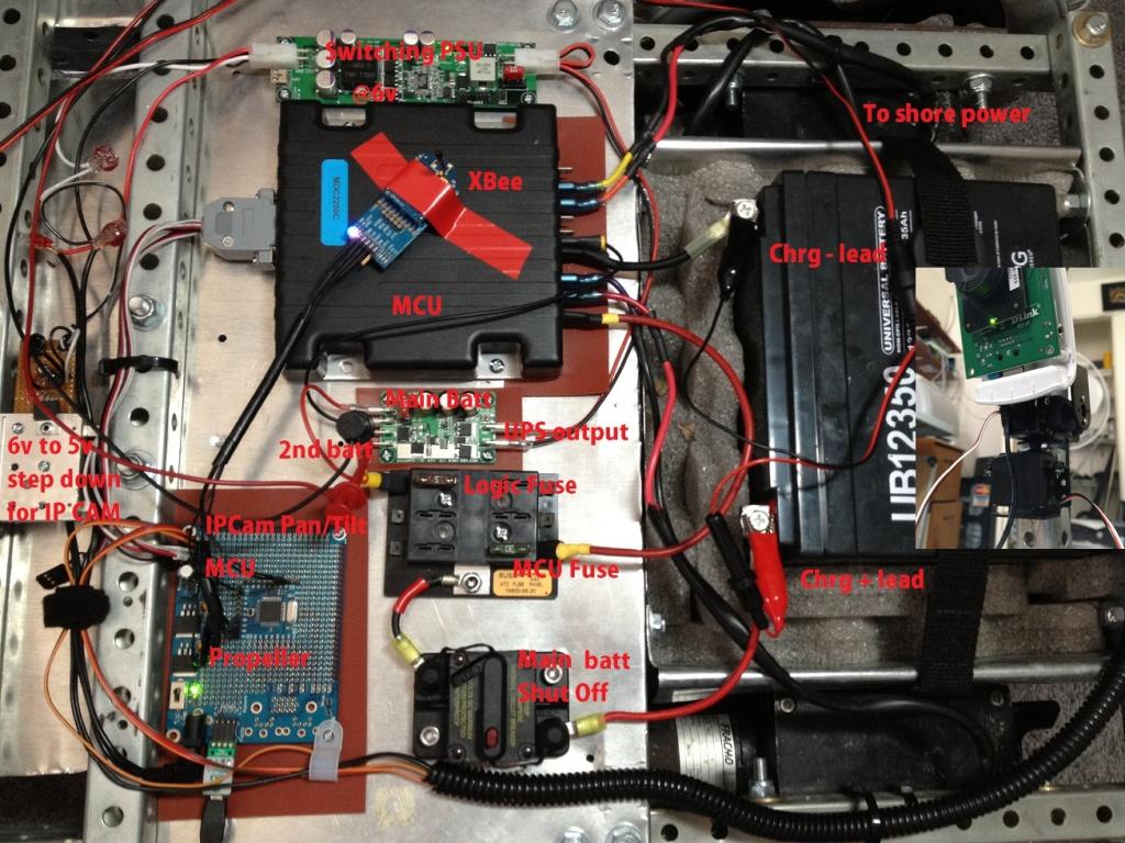
The charger is 14.9V @0.75A max loaded, it would be directly attached to the 12V battery. The 12V battery is also attached to a switching power supply with a rated input of up to 28V and also my MCU which has an input rated up to 28V. I would like these devices to be on while the robot is docked and charging.
Given those specs, my little trickle charger shouldn't cause any issues right? If the onboard electronics can handle up to 48V and they're in parallel with the battery which is 14.3V max?
Arcing won't be an issue because the dock will turn on the charger after the contacts have been made, not before. But is there something I should put between them anyway?
My concern is if I connect my robot into a docking station and charge the battery should I be disconnecting the other electronics from the battery?
The charger is 14.9V @0.75A max loaded, it would be directly attached to the 12V battery. The 12V battery is also attached to a switching power supply with a rated input of up to 28V and also my MCU which has an input rated up to 28V. I would like these devices to be on while the robot is docked and charging.
Given those specs, my little trickle charger shouldn't cause any issues right? If the onboard electronics can handle up to 48V and they're in parallel with the battery which is 14.3V max?
Arcing won't be an issue because the dock will turn on the charger after the contacts have been made, not before. But is there something I should put between them anyway?
1024 x 768 - 146K
Comments
al1970- It's 1A I looked it up, it's a good quality charger and yes it will be working hard but it's fed from a 15w solar panel so it doesn't have much to begin with.
tobdec- Got any docking station secrets to divulge? The next part for me is the connector, I don't think the skid plate is going to work out. I was thinking about running two dual mounted banana plugs, female set on the bot and male set on the dock. Then running the robot into them. Seems like there's got to be better ways than that.
xanadu: I do not have a pic up yet but this is my current project with a docking station http://forums.parallax.com/showthread.php?139970-Business-card-presenting-bot now just imagine that with slot car contacts on top and a 3rd one for my PIR sensor input with a garage type structure overhead and reed switches to tell it when its docked correctly. Albeit my bot is much smaller than yours by the sound of your battery. However I do know of a design that sounds like its just the ticket here....funny story my gf found this project while searching my name on google lol I have the same first name. http://letsmakerobots.com/node/7025 In this gentleman's design he used what looks to be battery terminal springs as contacts and a shaped delrin cutting board material as a guide...couple this with a few reed switches to ensure proper alignment and sensing and you may be ready to rock my friend!
Yes, that's great it would and the 12V socket is bigger making the alignment easier as well.
That has me thinking about sockets, especially wall sockets, and the fact they're in every room. Maybe I can use a small wall-wart style charger on a fold out arm, and drive it into a wall socket with some PING guidance. Then for my solar docking station use an inverter and a wall outlet and a heavy weight in the bottom. That would solve a lot of problems and work elsewhere. I like it!
Thanks for the ideas
I don't think I could custom fabricate anything along those lines. I have some nice designs but no means to build them. The robot is big enough that it should plug into a wall outlet. That solves a lot of problems, but now I need to figure out how to do it for less than it would cost me to fabricate the skid plate approach.
This is loosely what I want it to do, but articulating and also on the DC side will be a relay so that the charger pulls no power from the wall outlet until it's seated.
Docking and undocking. You can see the charge light on the charger light up. I probably should annotate the video. It's raw footage of the first time I tried. The long pause before the hand wave in the middle is because the motors were in neutral and I had to run to my bedroom and fix that.
With a battery that big, you probably won't need to recharge all that often.
"al1970- It's 1A I looked it up, it's a good quality charger and yes it will be working hard but it's fed from a 15w solar panel so it doesn't have much to begin with."
Tobdec, I'm not sure what you mean, a pic would be awesome. So I don't hijack my own thread I'm going to post some of the design ideas I had here as well.
Al1970, I should have wrote 1 amp continuous, instead of max and 0.75A is the highest I've seen it go while charging. I have no idea what the max rating is, I'm sure that it's at least 25% higher. Sorry for confusion it just follows me wherever I go.
http://schursastrophotography.com/robotics/dockinglogicfinal.html
My 'bot is much larger, so the full-frontal contact plate scheme wouldn't work, but the hoops for charging contacts are great. For my nest, I used brass strip metal -- it conducts pretty well and maintains it's "spring". I use two IR detectors with about a 6.5" inch "vane" between them -- both detectors see the nest IR beacon only when the nest is dead ahead. Actually, it's within 6 degrees or so. See attached for a simple diagram I used to estimate accuracy.
Given that we have a number of 'bots out and about here, all the 'bots -- and this big 'bot's nest -- use an IR code, sort of like Sony SIRCS. This lets them send simple messages, as well as prevents IR "pollution", clobbering IR obstacle detectors, etc. The big 'bot sends an IR message out when he's hungry asking the beacon to turn on. When the beacon receives that particular IR message, it starts sending an "I am here" message -- once the big 'bot picks up the docking station's IR messages, it can use it's two detectors to home in on the nest.
The 'bot knows it's charging with simple zener diode and 1M or so resistor -- with no charging current on the front contacts, it's a logic low, otherwise high. This let's the robot stop, of course, but also send a brief IR message to the nest to tell it to "shut up".
Both the nest and the 'bot are protected with fuses right by the contacts and hefty diodes to prevent possible short circuits (w/o blowing a fuse) on the front contacts. I wired up my own charger -- basically a 1.5 amp constant current charger. A recycled printer table top power supply provides juice (the main diodes and the current limiting regulator help drop the 16.5 volts from the printer supply down to a 13.8 volt or so charge current.
I'm not sure what Erco meant about an inrush of current to the battery/on-board supply if the fuse blows -- if the fuse from the charging contact to the 'bot's battery blows, then the charger is effectively disconnected from the 'bot circuitry.
xanadu: I know my pic is cheesy as hell but let me know if you understand this or not
Commercial 'bots like the Rovio, which has charging plates on the bottom, are similarly protected.
Tobdec I see what you mean with the cone and will definitely take that into consideration. The cone shape gives a lot of surface area and should be easy to line up. Also the female cone side should offer a lot of short circuit protection and I'd put it on the robot side.
I have decided that for my original hurdle, what to put between the battery and charger, will be this;
Batt+>fuse>diode>N.O.relay> |dock| <diode<fuse<charger+ w/thermal and overload prot
Batt->fuse>diode>N.O.relay> |dock| <diode<charger- w/thermal and overload prot
My reasoning for the relay is I do not want the charger attached to the battery (yet). Since the charging amps are low it's not going to take a big relay to do this. This way if there are any docking issues it won't matter because the circuit will never complete until there is a solid capture of the docking power.
The other relay concern is, I'd rather not have any exposed contacts. So the relay would allow for exposed contacts with the least mechanical process involved in protecting them. I'm trying to design this robot with harsh environments in mind.
Thanks again guys! I'm going to throw together something this afternoon
Same here. I was going to go with a more complicated cone&probe but that looks much easier and simple to construct.