Burnt up Propeller chip, Eddie Firmware and Saabertooth 2x25 Whats happening here?
I don't under stand whats going on here.
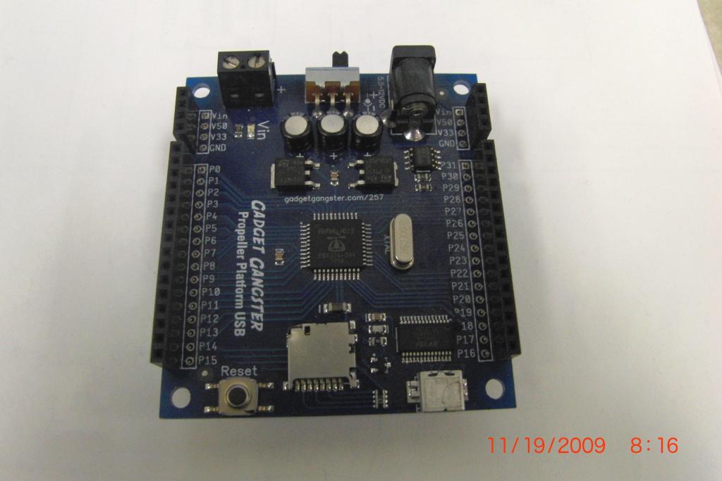
I have a Gadget Gangster propeller board. Powered by a 7v Rc battery pack.
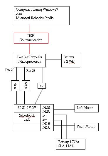
I loaded the Eddie Firmware onto it for my robot.The Eddie Documentation shows that on the Eddie control board shows pin 20 and 23 on the propeller are the PWM outputs to the H bridges for the motor controller.
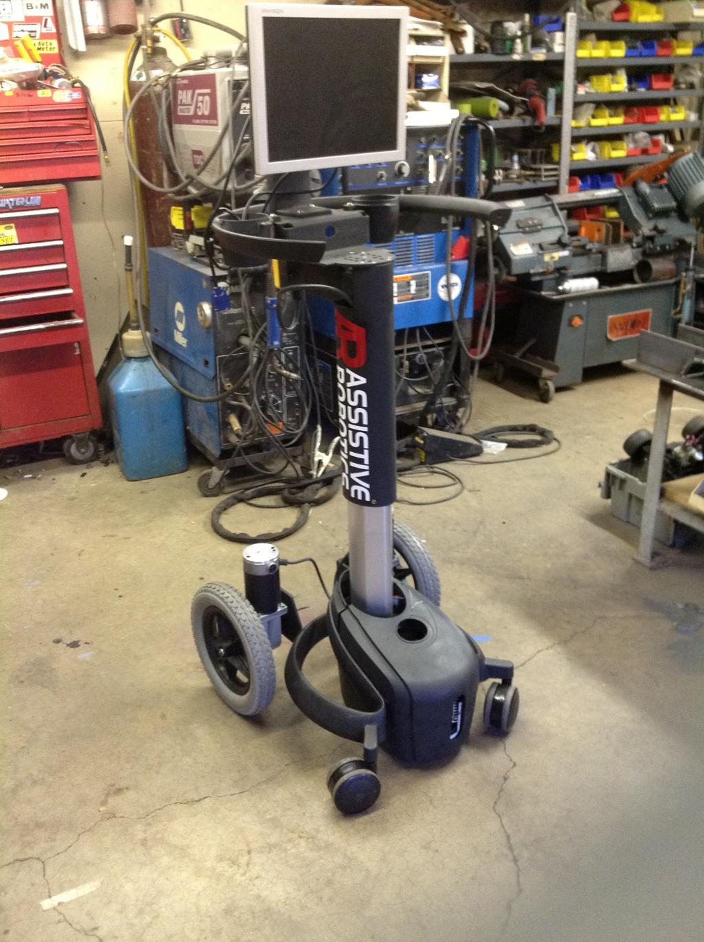
To drive my 350 watt wheel chair motors I'm using a Dimensional Engineering 2x25 saber tooth drive. That accepts the 2 PWN outputs and a ground signal from the Propeller board.
I start the Eddie program in Microsoft Robotics Studio.it loads. The drive console comes up and I push fwd on the X Box controller and the wheels move. So it works.Not to well but it works.
Some times the wheels will just keep rotating.
I disconnect the 12v power from the 2x25 motor drive but the wheels keep turning with no power connected to the drive.
Then I turn off or disconnect the battery from the Propeller Board bu the wheels keep turning.
I finally unplug the USB cable fro the laptop to the Propeller Board and the wheels stop.
Now it seems I lost the ability to connect to the Propeller board as my Propeller/Spin software wont recognize it. I have other Propeller boards that get recognized but this one wont anymore.
I need to figure this out cause I cant afford an Eddie board and I cant afford to keep burning up any more board.
Any help or theories would be appreciated.
thanks john


Comments
Also I see no information in the Sabre Tooth documentation that suggests it is 3.3V compatible in the first place. Perhaps you should buffer the Prop outputs with a 74HCT buffer running off 5V?
I would definitely buffer the output of the Propeller where it connects to the Saabertooth controller. To start I would use 1K resistors which will help protect the Propeller. That is a common size to use when connecting servos. Some servos may need a higher value and others almost nothing but a value of 1K is a good place to start.
I've run into a couple instances where that wasn't enough. In those cases I've had great results using a 74HC14 chip in between the Propeller and the device. I use a couple of the inverters back to back so the signal isn't inverted. The result is a nice clean 5V signal on the output. You can condition 3 lines this way. If you only need two for the drive motors make sure you connect the inputs of the two unused gates to ground.
Robert
After all, boards generally require two types of connections - complete power and complete I/O.
No need to isolate or buffer the communication lines with resistors or other ic's as long as the data sheet specs are maintained, there is never a reason to add parts. People always make this assumption and I just chuckle.
It's ok to disagree but the data sheet usually shows what it "should be" and they don't always show a schematic of what the actual inputs are in the controller. Also, it doesn't mention what can happen when the motor controller melts down and ends up connecting the motor battery power to the logic inputs, Even though that is unlikely it can happen and I have seen people do that before. That is why I recommend starting out with at least a resistor as some sort of protection. Resistors are a lot cheaper than a new Propeller chip.
The 5V connection is an output from the board's BEC. You can use it to power a uC. You shouldn't try to connect a 5V supply to it.
The problem is in these three statements, and the likely result is that the Propeller is probably damaged.
If you disconnected the motor power supply and the motors still turned it means power was being drawn parasitically through the Prop's I/O pins. This is *precisely* why you use buffers, opto-isolators, or at least series resistors when connecting to high-amperage components. Unless you know the inputs of the motor driver are protected from this very thing -- and apparently they are not -- it's always wise to provide the protection yourself.
Opto-isolators are the safest when connecting to high-amperage drivers. Most can handle typical PWM, even ultrasonic.
-- Gordon
@Loopy,
As I read the data sheet, the 5V is for powering external devices. As the Propeller Boars is already powered from 7.2V, this connect is not needed.
EDIT: Duane beat me to it.
Since I did this the first time last I have got a new drive from the people at Dimensional Engineering.
For the Propeller board I tried on several different usb cables and computers and still cant connect. I can plug in a different propeller board and it will see it.
Also it seemed my USB port on the computer shut down cause it didn't see com2 for a while.
The maker of the saber tooth Dimensional Engineering suggest this filtering
The 5V is to power external thing like a RC receiver
That's the weird how does the 5v from the USB port make it to the motors? Good thing I had them off the ground so it didn't pull that many amps.
I would have thought this board would have provided some form of protection. I tried to find out by looking at a schematic. I couldn't find a schematic for the board anywhere. It bugs me when manufacturers of electronic devices (particularly hobby electronics) don't provide schematics!
Now we can't find out what kind of protection the board has or doesn't have without reverse engineering the board.
My sympathies to you. I wish it weren't so. But there are lots of hobby manufacturers that write slick add copy, but are slow to really document or support their devices. In some cases, there is excellent support, but real proprietary issues. However, just as often it is a matter that a small business doesn't consider the overhead of documentation and support.
Parallax holds itself to a higher standard than most. And so, I keep turning to their products.
I find it very odd that you have observed 5VDC from the USB going all the way to the motors. Since the output of the Propeller I/Os are only 3.3v it doesn't seem possible - UNLESS there is a serious wiring error. Power from the 7.2V battery is far more likely to be turning the motors. But you seem to have proven that the USB 5V at 500ma is driving them via a damaged Propeller and via the PWM I/O.