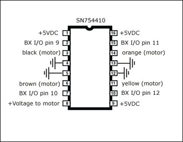
Ok so I have a robot project over in the projects area and have an SN754410 hooked up to drive my motors.....the Homework board im on can't supply enough amperage to drive the IC. So I am going to go to batteries plus today and pick up a rechargable battery. Heres my question: I know that I can basicly put whatever voltage of battery I want to the stamp bc it has a voltage reg built in easy enough.....and I know how to give the positive and correct voltage to my dual h-bridge IC....where do I out the grounds from the IC to? Do I connect them to the stamp's ground? or directly to the battery? Or does it even matter...I know it's a noob question but I simply don't know the layout of the HW board. Here is a schematic the 4 ground are the middle 2 pins on either side. If my thinking is correct these will go directly to the battery...correct me if imwrong I just don't want to fry anything.

 tobdec
Posts: 267
tobdec
Posts: 267


Comments
I'd uses a heavy duty wire to connect with the motor and just a normal signal wire to connect to the HW boards's ground.
I seen debate on whether or not the SN54410 needs external diodes or not. From what I've read, I think they should be used. I believe the sample circuit in the datasheet shows external diodes being used.
The coils of the motors resist changes in current flow. If you try to change the current too quickly the motor will create a voltage spike as it attempts to keep the current flowing.
Since it is difficult to be sure you're not going to shut off the current too quickly, it's generally a good idea to use flyback diodes with inductive loads (motors and relays).
The 754410 is pretty inexpensive if you want to test it, and should it not work you can usually fall back to the L293D. But even then, there are so many $5-10 dual bridge modules now out that use more modern techniques, and are already well protected. A bit more than a bare L293D or SN754410, but better peak amps and often better PWM handling. Look, for example, at Pololu's TB6612FNG dual driver carrier. About $8, 3A peak, 1A continuous, itty-bitty board easy to integrate anywhere.
-- Gordon
I based my earlier recommendation on this diagram.
I see now, it is for using the chip with a two phase stepper motor.
This next diagram shows the internal diodes.
I've read debate about whether these internal diodes offer enough protection. I'm not sure if the internal diodes provide adequate protection (what do flyback diode protect? The uC or motor driver chip?)
I'm inclined to trust Gordon's opinion on this matter. I believe Robert also said the internal diodes should be enough.
I'm not sure if the BS2 can provide a PWM signal these chips can use. I believe there is something a bit odd about the way the BS2 does its PWM that limits it usefulness in some applications.
But as I said, I think the overall best approach is just skip these late 20th century relics and go with something newer and more efficient. For just a couple more bucks you get a lot more functionality.
For $25-30 you can get a serially-controlled motor driver, which will then do PWM, dynamic braking, etc. Parallax resells one or two of the Pololu drivers, though I'm not sure they carry any of the serial ones. These are nice because they are set and forget.
I've used this one in several projects:
http://www.pololu.com/catalog/product/1110
-- Gordon
The stock Tamiya motors are of pretty low quality. They're also only for 3V operation, and at 5-6 V they pull several amps when stalled.
I highly recommend upgrading the motors with these:
http://www.pololu.com/catalog/product/1117
These are meant to be used at 6V and even higher, and at 6V have a stall current of 800 mA, well within the range for the 754410, or the only "new-and-improved" bridges I've been describing.
Even with these better motors it is not uncommon for one to go faster than the other. Fixing this depends on your application. For a line-following bot it's of little or no consequence.
-- Gordon
edit: I actualy got it pretty damn straight now...I simply swaped the motors...voila! It ran over 4 ft in a straight line....huge improvement! So basicly I just gota get my black line sensors hooked up and the dvd-rom drive and its done. Gordon ima go ahead and order a few of those motors anyhow, im sure theyll come in handy..plus theyre cheap and a whole lot better with the voltage rateing than my stock ones.
I can see the advantage of using one of those controllers if your using a single core microcontroller, but with the Prop, it's not hard to send PWM signals to a controller.
I switched from SN754410 chips to L298N chips in my Mecanum wheeled robot.
While the SN754410 chips used to get hot (even doubled up) the L298N chips don't even get warm running the Rover 5's motors. SF's price for the L298N chips is pretty good (better than Dig-Key's price) so the L298N chips don't cost a whole lot more than the SN754410s.
The L298N can be persuaded to fit on a breadboard.
This isn't much help with the problem of powering a motor from a BS2, but I think these chips are worth keeping in mind for other projects.
I have a real issue about that SparkFun L298 board -- one of their poorer designs, and I see they still have 1,000+ of them! There aren't many 2A bridges out there in the price-range, though, so we put up with it.
-- Gordon
and Gordon this link is for you http://www.ebay.com/itm/Heathkit-Zenith-Hero-Jr-Robot-Vintage-Home-Robot-no-charger-included-has-batteri-/110875648227?pt=LH_DefaultDomain_0&hash=item19d0b420e3 I know ur into vintage bots...havnt seen any pic of this particular model thought you might be interested!
I can find several different L298 boards at SparkFun. Since you mentioned they have over 1,000 of them, I'm guessing you mean the little breakout boards I used above.
I'd really like to know what you don't like about them.
I don't like they didn't add any easy way to add diodes and the power traces seem on the thin side but I'm not sure what's not to like since the board just makes it easier to connect wires to the chip.
I've recently taken up PCB design in order to make some boards for some magnetic encoder chips I like. Since I have a second Rover 5 chassis, I've been seriously considering making a PCB with two L298s, a Propeller and places to hook up motors and encoders of the Rover 5.
The Rover 5 version SparkFun sells has quadrature encoders on all four motors. I haven't seen any examples (other than my robot) of all four encoders being used with the chassis. I'm hoping to make a board that would make it easy for Arduino users to take advantage of the Rover 5's encoders.
If you think the L298 isn't a good match for the motors of the Rover 5, I'd like to know if you have any suggestions for a better motor control chip (hopefully inexpensive).
As I mentioned earlier the SN754410 chips I had previously used with this robot got very hot after a few minutes of use. I haven't ever felt these L298 get even warm when I've used them with my robot. I took the lack of heat as a good sign.
Exactly. The board is just not well thought out. For the same money and footprint they could have added pads for the diodes. Some pads for bypass caps would have been nice, too. Really nothing more than the basic parts for the reference design that's in the datasheet. And yes, they really need to go on the board. The closer to the chip the better.
Apart from the occasional limited run board I see here and there, the SF breakout is about all we have to select from, and you're right it's better than nothing. But I just think they could have put a little more time on it.
>>I took the lack of heat as a good sign.
Or the high internal resistance of the L298. I'd be curious what voltage is actually reaching the motors. You might try a stall test to see how much current is drawn. The heat dissipated from the chip is really just a function of current. With one you get the other. You can always bolt on a piece of aluminum bar if you need to enlarge the heat sink area. That's a nice feature of the Multiwatt package.
To be fair there are things I don't much care for in the Pololu designs. They take more time on their designs, and they produce very detailed documentation. But they're on a miniaturization kick that's so extreme many of their boards have no meaning for mounting. If you want something solid you have to resort to cable ties.
-- Gordon
-- Gordon
Amen to that. (Or should it be "Words from the wise!"?)
Thanks for the help Gordon.
Particularly when L298N chips with diodes are so cheap.
This L298N board which is populated costs 15 cents less than the bare board you're selling.
Parallax does have a classified forum which I think is a more appropriate place to promote your website (I'm not sure if it's completely appropriate even there). Posting here comes across as spam, particularly when it's a reply to a post made ten months ago.
Edit: Actually, I don't think it would be a problem to promote your website here if it's done in a manner similar to the way Andrew does. No one minds Andrew including a link to some of the things he sells in his signature when it's part of a genuine (and generally very helpful) post. IMO, the way you're promoting your site comes across as dishonest.