PEKit: Cannot make RCDecay to work
So far, Propeller Edution Kit was fun and easy. Currently I am stuck with RCDelay example:
The lab expects the following schematics:

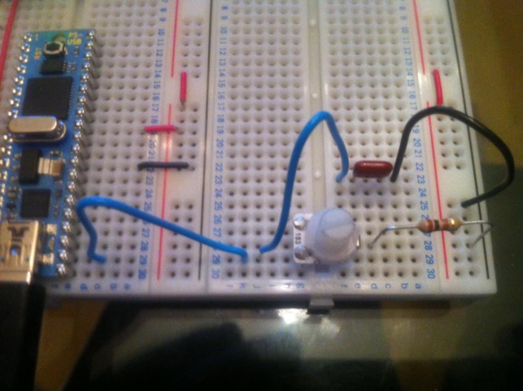
My circuit is as following:

I use 103 capacitor which should be 0.01 μF.
The spin code is from lab "TestRcDecay.spin" (unchanged) (I attach it here as well)
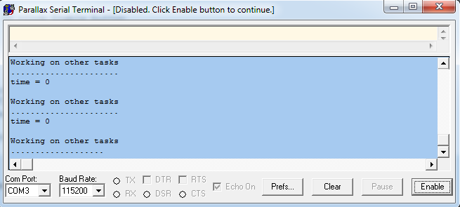
When I run the program it returns me constant 'time = 0". Turning potentiometer knob does not help...

Any ideas are appreciated.
Thank you,
Dimitri
The lab expects the following schematics:

My circuit is as following:

I use 103 capacitor which should be 0.01 μF.
The spin code is from lab "TestRcDecay.spin" (unchanged) (I attach it here as well)
[ATTACH]92215[/ATTACH]
When I run the program it returns me constant 'time = 0". Turning potentiometer knob does not help...

Any ideas are appreciated.
Thank you,
Dimitri


Comments
I highly recommend to insert a 150 Ohm resistors between each propeller-IO-pin and the thing you want to connect.
I mean this way
Prop-IO-Pin-No 0
150-Ohm
anything you former connected to the IO-Pin
Prop-IO-Pin-No 1
150-Ohm
anything you former connected to the IO-Pin
Prop-IO-Pin-No 2
150-Ohm
anything you former connected to the IO-Pin
....
Prop-IO-Pin-No 31
150-Ohm
anything you former connected to the IO-Pin
Why this?
This will protect the prop-IO-pin from sourcing or sinking too much current if you accidently connect them to either +3.3V or 0V.
This short peace of wire has a resistance of 0,1 Ohm.
Now imagine you have programmed the IO-pin as output and set him to +3.3V and connect it through 0,1 Ohm to ground.
current 3.3V / 0.1 Ohm = 33A (theoretically). As the current rises something inside the propeller-chip will burn through.
You are a lucky guy if this hasn't happened. Now with 150 Ohm inbetween
3.3V / 150 Ohm = 22mA. Which is a save value. (Each IO-pin can drive 30 mA).
Additionally I recommend examining carefully how each whole on your breadboard is connected to the others.
Reading basic materials about electronics is a good idea too.
This is a website that explains the things in a quite good to understanding way. (which is seldom on the internet)
http://openbookproject.net//electricCircuits/DC/index.html
best regards
Stefan
Thank you, kuroneko! You were exactly right it was not doing anything. Once I changed layout, RCDecay started working just fine:
Re: Stefan's suggestion:
I agree with your suggestion as a rule of thumb. However, PEKit documentation explicitely addressed this approach for potentiometer exercise. Here is a quote from page 127:
I guess I was just like that I didn't burn my Propeller chip.
Thank you for your suggestion.
dimitri