

Please Help With IR Module
 kenwtn
Posts: 250
kenwtn
Posts: 250
Hi All,
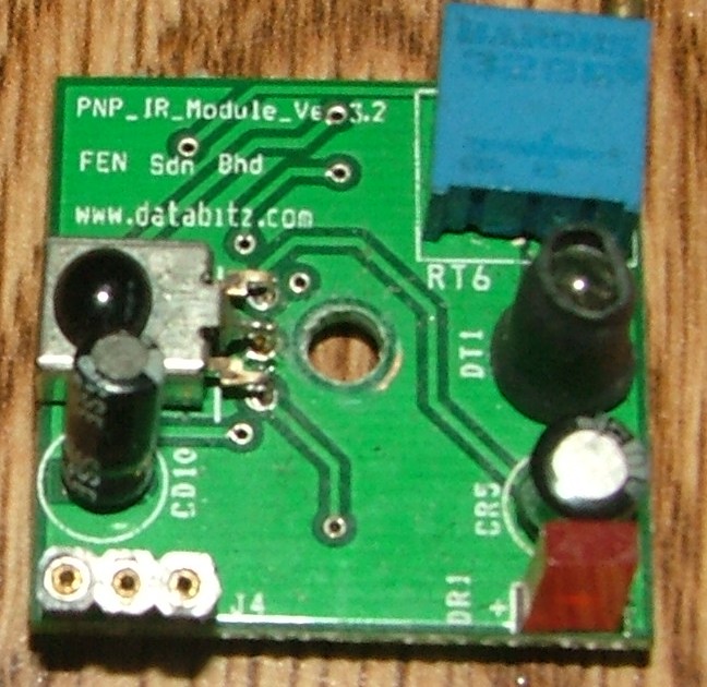
It has been several years since I worked with the Basic Stamp. Years ago I purchased several if these IR Module off EBAY and I did use a few of them in a project I worked on years ago. Anyways to make a long story short I m not sure how to connect to the Basic Stamp. The IR Module has only 3 connections I believe they are VDD,VSS and signal in that order from inside to outside of the board. But again I can't say that for certain. I did send email to DATABITZ.COM as that is on the board and I also went to their website but could not find this board. My hope is that maybe someone here may know about this module and can help me with connections and use.
Thanks,
Ken
648 x 630 - 121K
634 x 619 - 138K
Comments
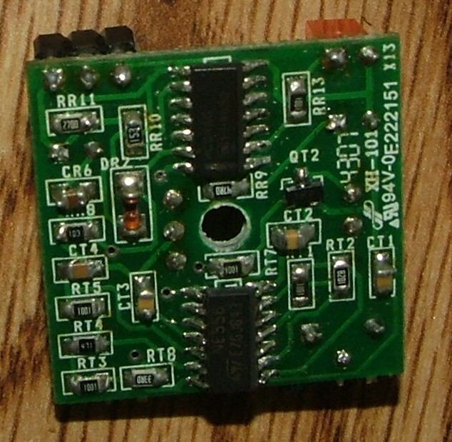
It seems that this module has no voltage regulator chip. The electrolitic capacitors probably are connected to vdd and to vss.
Measure the resistance between negative capacitor terminal and one of the connector terminal. If it is close to zero Ohms, then this terminal is VSS.
Measure the resistance between positive capacitor terminal and one of the connector terminal. If it is close to zero Ohms, then this terminal is VDD.
The remaining connector terminal is signal.
You must be verify if the output is the open output kind as well.
If you are still unsecure about the connections after these measurements, try to put a 470 Ohms resistor in serie with two of the connector terminals (on for each terminal). This can prevent this module (and the module that will control it) to be damaged.
Of course after making this module working, you must remove these resistors.