

Stingray Robot Kit (#28980) and Wheel Encoders
 Chris Savage
Parallax EngineeringPosts: 14,406
Chris Savage
Parallax EngineeringPosts: 14,406
Hello everyone,
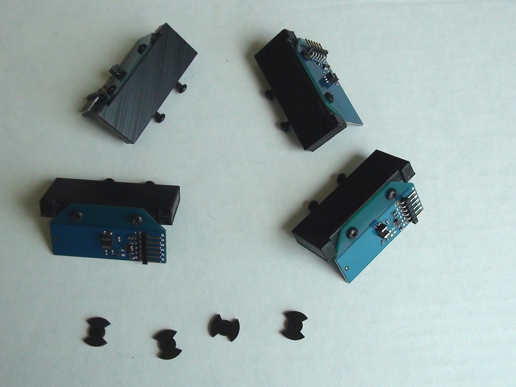
I wanted to update you on the status of our ongoing Stingray improvement plans. The first thing we wanted to do was get more motor options (still waiting on samples) as well as some wheel encoders. I have been working with Matt Gilliland to bring to you an encoder that will work with more than one product, but mainly to bring encoders to the Stingray Robot Kit. I am happy to say that I was recently sent the following items from Matt G. which represent the first prototype wheel encoders that will be compatible with the Stingray.
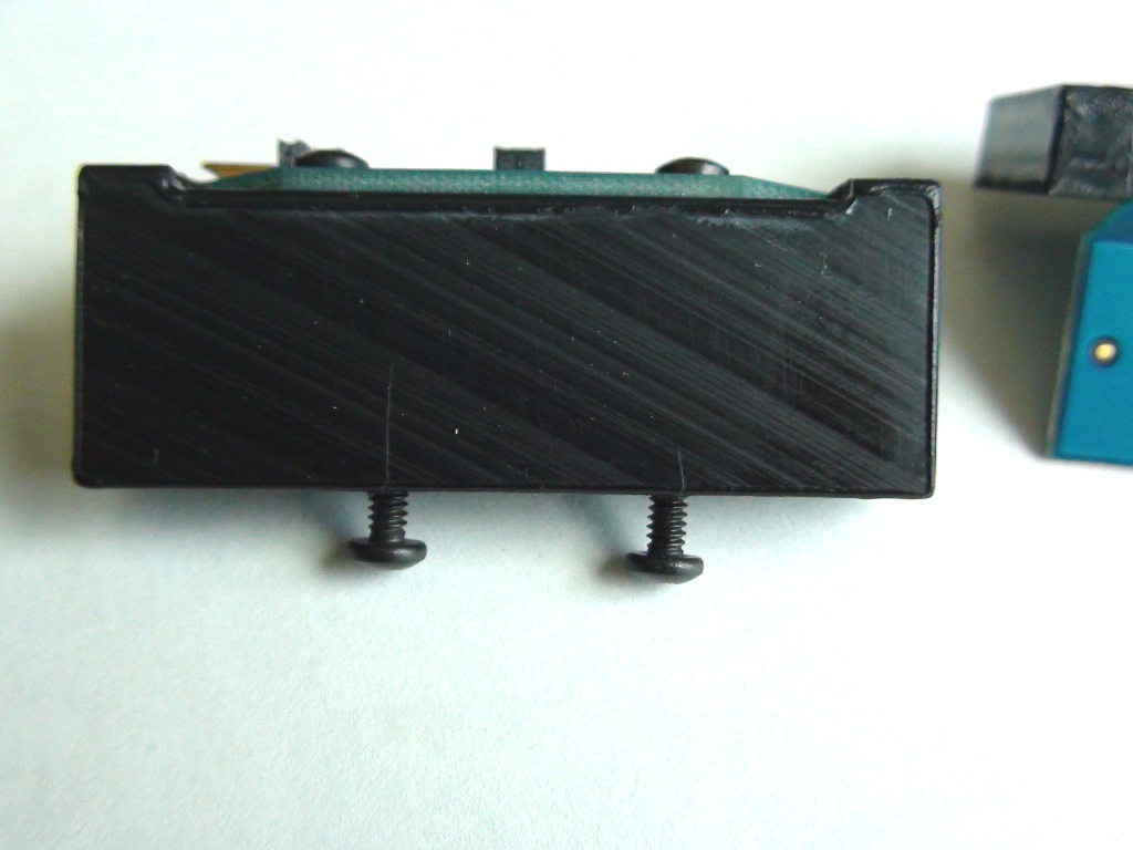
Each unit consists of a press-fit plastic encoder disc, encoder PCB with quadrature sensor and laser-cut mounting blocks to adapt these to the holes near the motors on the Stingray. Now these are hand-built, hand-assembled units, so not necessarily what the finished product will look like, but I will spend some time this week testing these and Matt has been testing them in other systems.
(CLICK TO ENLARGE PHOTOS)
Matt said he will provide detailed documentation explaining how to use these with the Stingray and I will be providing some code in the near future.
I wanted to update you on the status of our ongoing Stingray improvement plans. The first thing we wanted to do was get more motor options (still waiting on samples) as well as some wheel encoders. I have been working with Matt Gilliland to bring to you an encoder that will work with more than one product, but mainly to bring encoders to the Stingray Robot Kit. I am happy to say that I was recently sent the following items from Matt G. which represent the first prototype wheel encoders that will be compatible with the Stingray.
Each unit consists of a press-fit plastic encoder disc, encoder PCB with quadrature sensor and laser-cut mounting blocks to adapt these to the holes near the motors on the Stingray. Now these are hand-built, hand-assembled units, so not necessarily what the finished product will look like, but I will spend some time this week testing these and Matt has been testing them in other systems.
(CLICK TO ENLARGE PHOTOS)
Matt said he will provide detailed documentation explaining how to use these with the Stingray and I will be providing some code in the near future.


Comments
Paul
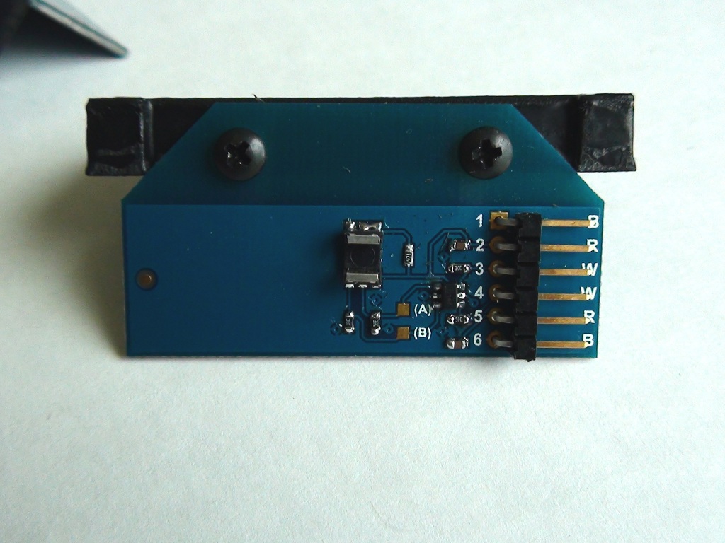
Very simple encoder. The sensor itself is a dual unit with two detectors looking at the same emitter. There's a dual schmitt-trigger with pull-downs and a 1 x 6 header that provides a convenient way to attach power and get either one or both signals out to your device.
The original idea for this device was to replace the "smart" dual encoder that is currently in the Eddie and Madeusa Robot platforms (although I think we should hang onto the others for a while for Legacy sake...do you think?
These encoders should quite a bit cheaper because there are no thru-hole devices - the thing is Pic-n-Placed. (it's my personal goal to drive the cost of our platforms down to rock-bottom prices - a robot in every home, I say!)
The encoders will be available by themselves, and then we'll also have a "Stingray Encoder Adapter Kit" that will be available separately. Should be in production in about 2 weeks.
-MattG
In the first picture, what are the bow tie parts? When Chris said it was press first on the wheel, was thinking 1 disk per wheel.
Those are "Balanced wings" that block the opto-sensor, twice per revolution. Because the Stingray has a very high gear ratio, this sensor disk only really needs one "pulse" per revolution - but it would throw the shaft out of balance, so we made it with two pulse capability.
When used on the Madeusa or Eddie, the sensor mounts on the output drive shaft of the motor so there's "36 pulse fins" per revolution. This may be increased, or we may include a couple different "pulse wheels" in the kit for different resolutions per revolution...say that 3 times fast.
-MattG
Thanks for the explanation Matt, but I am still not seeing it clearly... When I look at the StringRay wheel, its not clear how anything can press into it. Also when looking at Chris's pics, it isn't clear how that will mount on the StringRay. Any pictures of the test wheel setup? I am sure that would clear it up for me. Thanks! Maybe I have my wheel to close to the chassis so I can't visualize putting something between the wheel and the chassis...
I'm sure when these are available, the product description will explain everything clearly.
So far I'm a little confused.
for example: one of these for 2 motors?
A picture is worth several words.
Here's a little background, and hopefully some clarity...
The circumference of the Eddie/Madeusa drive wheels are about 19". The backlash on the motor drive unit is just shy of 1/2" at the 3" arc that the wheel rotates around (6" dia. wheel). This would indicate that the best resolution we could expect would be about +/- 1/4 of one inch.
Our (old- but still in production) encoder had two separate "single sensor" optical devices that were separately mounted on the PCB. The new encoder (shown in Chris' pix above) contains a single optical module that has (1) Led source and (2) detectors contained within the same slotted piece of hardware. One of these new encoders is required for each wheel that you wish to "track".
That being said, the new encoder also uses a new encoder wheel - it's the one on the right is this pic: The encoder wheel on the left is from the (old, but not obsolete) controller.
The OLD wheel has (9) fins.
The NEW wheel has (36) fins.
This should result in a 4X improvement on rotational resolution (except for the aforementioned backlash).
The (9) fin results in (18) transitions x 2 channels = (36) "resolvable steps".
The (36) fin Newbie results in (144) resolvable steps.
Given the gear housing backlash of +/- 1/4", and an 19" circumference wheel, this results in: 19" / 144 resolvable transitions = 1/8" + or -.
Bottom line: Higher resolvable accuracy, lower cost, simpler integration, access to the raw data stream, and it will work in the MadeUsa, Eddie, and Stingray Robots (separate hardware mounting kits will be sold separately).:thumb:
-MattG
[sarcasm on] and you do it very well [sarcasm off]
Thanks for the additional information. I will be keeping my eye on these developments, motors, encoders, etc.
(main interest is for the Stingray)
I think those are meant to press onto the motor shaft, opposite the gearbox.
Or will this require the Stingray Chassis Kit?
Either way, I want one too! I gotta try and give Stempile a run for his Line Following money..
-Tommy
Right you are W9!...but, as mentioned above, a pic will make all things clear. I'll get that pic up tomorrow am as well.
What's the matter with all of you? I can see it clearly in my own foggy mind- can't see through my foggy mind, huh?
-MattG
Hey Tommy- The short answer is Yes. However, I do need to check the elevations to see if the standard Stingray Bracket (that I'm currently working on) will fit. If not, I guess I'll make another "Mounting Kit" :thumb:
The cool part is that our Laser is getting a real workout, and these are such simple parts - the costs should be really small - which means we can charge "an arm and a leg" a make a pot-load of cash and the...wait, is this mic on?
-MattG
Or as Joe Biden was heard to say about Obamacare via that unseen mic, "This is a big ...... deal!"
And I can get that second or third mortage on the house to pay for the new encoder and wheel set instead...
...and for the Stingray. The disk is only two pulses per revolution, but they're on the motor shaft - not the (slow turning) output shaft (as they are on the bigger bots)...
-MattG
Before someone says it, unsaid in those words is that the Stringray version isn't true quadrature. Not that it's needed as you'll know direction, and you'll get plenty of resolution without the quad 4X multiplication. (Some creative coding to affect a pulse stretcher might synthesize quadrature timing anyway. I'd probably just ignore the B channel except to use it to watch for incomplete transitions.)
I'm glad you were able to find an SMT dual side-looker.
Now, what are your thoughts on using the existing engineering to make a version on a much smaller board with a single tab for mounting? (Add a notch to lock the tab into position; it doesn't have to be an actual mounting hole.) That would make it smaller and more adaptable to most any robot. The Stingray is a fairly largish bot, but I can see this thing used on many types and styles of robots. Even Erco might buy a pair.
Whaddyasay?? You'd have two SKUs, but I believe you'd sell lots of both of them anyway.
-- Gordon
I read the word, skipped the meaning. Apologies to original poster.
The info was clear, me fuzzy.
Gordon, why is this not "true" quadrature? Is it that the pulses are not 90 degrees out of phase?
We can still get the same information (direction of rotation), correct?
With these gear motors, it's highly unlikely you'll not know what direction they are turning unless they are being forcibly back-driven. In these instances, quadrature adds value because 1) it increase the effective resolution of the disc by either 2X or 4X (depending on how you count the transitions) and 2) it allows you to better discern between valid and invalid transitions. If the disc is sitting right at a transition the output of the optical vane could stutter and send long streams of pulses, even though the bot is not moving. You know the transitions are not valid if the opposite channel is also not changing.
The disc with 36 "fins" will also not quite produce equal mark/space signals, as the distance between the fins is larger than the width of the fins. This is probably okay as you can compensate in software (or the software just doesn't care). It *could* be a problem in hardware quad decoders, like the ones US Digital sells. Their chips are pretty tolerant of timing delays, and they include internal pulse stretchers. These discs are probably okay, but if the mark/space ratio is ever too asymmetrical, the chips no longer perceive the A/B channels as quadrature, and the output is erroneous. Since these discs are being done on a laser there's always the opportunity to fine-tune their geometry, should it be the case that hardware decoders can't handle them. But again, the spacing of the 36-fin wheel is probably close enough to do the job.
-- Gordon
The OLD Encoder had two separate sensor modules that were thru-hole soldered after the boards had gone through the Surface Mount. We were able to space the distance between the two sensor "beams" to be exactly the width of each fin (see the pic above). The space between two fins (the "valley") was the same distance as well. This yielded a perfect (as perfect can be) 90 degree out of phase signal pair.
Now, look at the Stingray. Although the "wings" are (should be) the same width as the "valleys", it doesn't matter, because the Single Surface Mount Sensor that we're using has the "two eyes" that are really close together. What this means is that we'd have to have the Stingray disc with fins that are VERY, VERY, TINY (probably rectangular slots), and LOTS of them. Now, since this is attached to the drive motor (very fast), that would be a huge amount of pulses for very little actual distance traversed. As it stands, at full motor voltage the second wing trips approximately 50uS after the first wing does.
Also, because the fins would have to be symmetrically spaced, and very close to each other, the sizes of the "valleys" would be super-tiny, and the "fins" would be really thin - easily bent or broken.
But yes, you'll still get direction information.
Now to the Madeusa/Eddie platforms. The encoders are on the drive-wheel output shaft. Since the quadrature output is properly produced when we have the valleys and fins spaced the same as the distance between the two sensors, and in this case our two sensors are VERY close together, the fins and valleys would be VERY tiny as well - not mechanically reliable. (Especially because these are not enclosed devices).
Now, that being said, and like Gordon suggested, knowing your speed and the necessary "correction factor", you could derive a very close value for the quadrature data in code.
Also, when you factor in the backlash within the drive-motors, we'd have way more granular data than would be necessary due to the 1/2" of "slop" in the drive system itself.
Either way, you'll still see "staggered pulses" that tell you which direction, and of course the rate that you're bot is traveling - make the calculations and you'll certainly be close enough to not care - simply because of the backlash (which in this case cannot be mitigated).
Yeah, more than I wanted to know too.
-MattG
-MattG
http://www.parallax.com/Store/Robots/RoboticAccessories/tabid/145/CategoryID/22/List/0/SortField/0/Level/a/ProductID/788/Default.aspx
That motor is being replaced with one that does have the motor shaft extended out, we just haven't received the correct samples yet.
I'm guessing the discs are fairly thick (1.5mm is thick for diffraction effects), and maybe the optical alignment isn't quite perfect. That and if the LED source isn't terribly bright, I can well see that the light going spends more time below 50%, resulting in longer off times (assuming a 50% threshold). Making the slots/holes larger could work, but it seems to me you can't undo a bigger hole, should the design need changing. What are you using to detect low/high values? I've found comparators to offer better flexibility than just relying on the threshold values of input pins. More parts, though.
Matt is using fairly thin acetal. I could never cut that thin on my CNC, but it's child's play on a laser. And that's exactly what's going on -- Matt is like a child playing with that laser machine!
-- Gordon
O' course that comment's coming from an old guy that still plays with robots...ya' gotta consider the source.
-MattG
The discs (wheels) are 5mm crystal clear acrylic and the slots are about 1.7mm, with about 1.5mm between. It is the on time that is longer, hence larger holes to increase the off time. The alignment will likely never be perfect since the sensor is diffused and sits four slots widths away. That would only affect the phasing anyway, not the on/off time balance.
As shown, the same encoder is used on each Stingray wheel, it's just reversed. The mounting brackets and hardware will be available as a separate kit.
The Encoders will be sold separately, without any mounting hardware. Then there will be a "Mounting Kit" for the Madeusa & Eddie robots, and another mounting kit for the Stingray (as depicted here). Who knows what other robot mounting kits we can come up with?
This is the prototype set in the pic. A *lucky*(?) customer will be getting this prototype in a couple of days to "test drive" with no documentation, no directions, and no code samples, and...and...let's see, what else can't I give them, to make it a real challenge?
-MattG