

Simulation for Op amps
 kelun1
Posts: 10
kelun1
Posts: 10
Hi guys,
I am trying to look for a simulator that allow me to construct this :
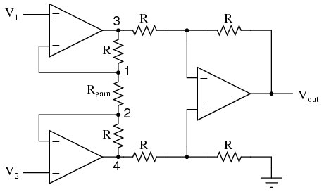
can anyone tell me which program that i can download online to do it? i have been looking around for it. =(
or maybe any program that can run this spice file
please help me as i need it badly for my project =(
and thanks alot of the help!
I am trying to look for a simulator that allow me to construct this :
can anyone tell me which program that i can download online to do it? i have been looking around for it. =(
or maybe any program that can run this spice file
INSTAMP1.CIR - 3 OPAMP INSTRUMENTATION AMPLIFIER
*
VS 2 1 SIN(0 1 10KHZ)
VCM 1 0 SIN(0 5 1KHZ)
*
* BUFFERED AMPLIFIER
XOP1 2 4 6 OPAMP1
R1 4 6 10K
R2 4 5 200
R3 5 7 10K
XOP2 1 5 7 OPAMP1
* DIFFRENTIAL AMPLIFIER
R4 6 8 10K
R5 8 10 10K
R6 7 9 10K
R7 9 0 10K
XOP3 9 8 10 OPAMP1
*
* OPAMP MACRO MODEL, SINGLE-POLE
* connections: non-inverting input
* | inverting input
* | | output
* | | |
.SUBCKT OPAMP1 1 2 6
* INPUT IMPEDANCE
RIN 1 2 10MEG
* GAIN BANDWIDTH PRODUCT = 10MHZ
* DC GAIN (100K) AND POLE 1 (100HZ)
EGAIN 3 0 1 2 100K
RP1 3 4 1K
CP1 4 0 1.5915UF
* OUTPUT BUFFER AND RESISTANCE
EBUFFER 5 0 4 0 1
ROUT 5 6 10
.ENDS
*
* ANALYSIS
.TRAN 0.01MS 1.0MS
* VIEW RESULTS
.PLOT TRAN V(2) V(10
.PRINT TRAN V(2) V(10)
.PROBE
.END
please help me as i need it badly for my project =(
and thanks alot of the help!
Comments
http://www.simetrix.co.uk/
The demo should be suitable for that circuit.
Hi! thanks for your reply!
i am downloading it now and trying it after it is done..
btw you happen to know any other simulation program that i can use to pull out and construct the circuit diagram that i show and run simulation run simulation and show an scope output or something after i feed the input with voltage or signals?
million thanks! =D
Hi! thanks for your reply!
the link looks great.. but it dont allow me to construct the circuit above! =(
any that you know of that allow me to do construction?
million thanks man! =D
-Phil
Hi! thanks for the reply! million thanks!
i tried this program before. but due to the lack of knowledge.. im unable to get any output =(
hi!
actually the schematic dont match.. the drawing is actually what i need to do.. and the file that i gave is actually what my lecturer gave.
im actually having to do this op amps simulation and show some output in my lab assignment.. so im looking for any recommendation that can allow me to like construction that schematic and run simulation and show an scope output or something after i feed the input with voltage or signals.
Out of curiosity, do you have any idea what this circuit is supposed to do?
from what i know the amp is suppose to take the different of the first 2 input and amplify it. am i right?
Yup - pretty much. The "front end" op-amps are buffering the input signals (maybe w/some gain) and the last op-amp is being used to take the difference between the two inputs (again, maybe w/some gain).
It looks a bit like this: http://www.ti.com/lit/an/snla140a/snla140a.pdf which may provide some insight.
Chapter 5 of this tutorial: http://www.electronics-tutorials.ws/opamp/opamp_5.html will offer the fundamentals of how the differential circuit operates. The whole section on op-amps is fairly well documented and easy to grasp.
It's always advantageous to understand what a circuit is supposed to do prior to simulation or construction so you know what to expect during debug.