

Basic Stamp 2 as a Racetrack Timing System - Programming Problems
 ryfitzger227
Posts: 99
ryfitzger227
Posts: 99
Hello everyone! I'm currently working on a project to where it will be used as a Round Track Timing system.
The way it works is a car comes around and breaks the infared beam. The infared then puts a neutral output. The Neutral output is connected to the neutral side of a relay.
When the beam breaks it sends a signal to the stamp. This signal is read as 0, and vice versa when it's in line & reflecting. You can go to www.bannerengineering.com and search Multi Beam Sensor's to learn more.
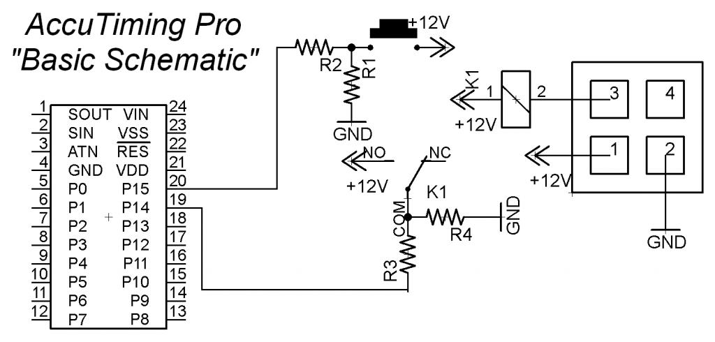
Check out the schematic attached to review the circuit. The Schematic is kinda messy, but it's okay.. Haha.
The program is also attached for you to look at.
Here's the problem:
When you read the program, you will notice there is a PAUSE SafeDelay (SafeDelay CON 2500) right after the do,nothing,loop until infaredinput = broke. Which means the timing would be off 2500ms. Well no problem, because it's added back after timing is complete. This is for "safety" because, for example the front tires could break the beam, and the rear tires also. So you would get a time like .025 or something of that nature.
Well it's inaccurate.... By a lot! If you use a stopwatch by hand, it will display, for example, 7.000sec. While the Computer (DEBUG screen) shows 3.800.
Please review the program and circuit to check for problems.
We race Saturday, so this needs to be fixed at least by tomorrow, so I can complete testing & know for sure that it works. Because we have no backup, and we don't want to get cussed out by angry racers... And maybe start a fight. Haha.
If you have a question, because i'm sure this is confusing, just ask!
Please help!!
& Thanks!
- Ryan
 Accutimg Pro v1.3.bs2
CIRCUIT INFORMATION:
R1 & R4 = 10K Ω
R2 & R3 = 220K Ω
Multi Beam Sensor info:
The multi beam sensor is the square block with 4 "terminals". Sorry, I should have noted that.
Terminal information for sensor:
1 = +12V
2 = -12V
3 = -12V OUTPUT
Btw: I didn't add any power or programming info on the basic stamp.. Just put pin identifiers. Sorry.
The way it works is a car comes around and breaks the infared beam. The infared then puts a neutral output. The Neutral output is connected to the neutral side of a relay.
When the beam breaks it sends a signal to the stamp. This signal is read as 0, and vice versa when it's in line & reflecting. You can go to www.bannerengineering.com and search Multi Beam Sensor's to learn more.
Check out the schematic attached to review the circuit. The Schematic is kinda messy, but it's okay.. Haha.
The program is also attached for you to look at.
Here's the problem:
When you read the program, you will notice there is a PAUSE SafeDelay (SafeDelay CON 2500) right after the do,nothing,loop until infaredinput = broke. Which means the timing would be off 2500ms. Well no problem, because it's added back after timing is complete. This is for "safety" because, for example the front tires could break the beam, and the rear tires also. So you would get a time like .025 or something of that nature.
Well it's inaccurate.... By a lot! If you use a stopwatch by hand, it will display, for example, 7.000sec. While the Computer (DEBUG screen) shows 3.800.
Please review the program and circuit to check for problems.
We race Saturday, so this needs to be fixed at least by tomorrow, so I can complete testing & know for sure that it works. Because we have no backup, and we don't want to get cussed out by angry racers... And maybe start a fight. Haha.
If you have a question, because i'm sure this is confusing, just ask!
Please help!!
& Thanks!
- Ryan
CIRCUIT INFORMATION:
R1 & R4 = 10K Ω
R2 & R3 = 220K Ω
Multi Beam Sensor info:
The multi beam sensor is the square block with 4 "terminals". Sorry, I should have noted that.
Terminal information for sensor:
1 = +12V
2 = -12V
3 = -12V OUTPUT
Btw: I didn't add any power or programming info on the basic stamp.. Just put pin identifiers. Sorry.

1024 x 490 - 59K

Comments
Unless you have some kind of external time source, the only way you'll get anything close to an accurate measurement is to eliminate everything from the timing loop except for the basic IR lap sensor, a time counter, and a PAUSE statement for the time "tick". A "tick" size of 100ms is probably reasonable. Something like:
I didn't include statements for checking the number of laps or for the end of the race, but this should keep fairly good time in units of 0.1s. At the end of the race, you can display the results. lapSensor is a PIN label. All variables are words.