Layout issue with USB, need feedback
 pedward
Posts: 1,642
So I got the PropKey boards back today, and after figuring out that I mirrored the USB pinout, I rewired everything. I started getting enumeration problems and so after looking into things, I'm pretty certain its because the flying wires I used are unequal length and it's messing up the USB comms.
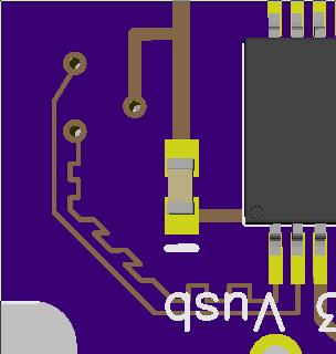
I revisited the layout to fix my errors and I adjusted the trace lengths to be equal. I looked at the Quickstart and found a little jog that was put into a trace to do the same thing, so I feel I'm on the right track.
I have posted a picture of the artwork below and wanted to get feedback on whether this looks okay or will cause me problems.
The trace lengths are now exactly the same length from the connector pads to the chip with this layout.


Comments
Also are you packing up the space below to make the board thicker? Otherwise could be intermittent contact. You could solder a cable to eliminate this.
http://www.4dsystems.com.au/downloads//micro-USB/uUSB-CE5/Docs/Pdf/uUSB-CE5_DataSheet_rev1.pdf
Actually unless the trace is buried there are two dielectrics involved, FR4 and air, so the air signal will take 10ps for the 3mm and the FR4 will take 22ps. Neither seems worth worrying about.
What is worth worrying about is the impedance of the transmission lines involved and whether there is cross-talk between the two signals - sort this out first before worring about 0.02ns of delay.
I put 22mil UHMW tape on the bottom of the board where it goes into the connector. This makes the overall thickness the same as a USB cable.
Do you have a .pdf of your schematic that we might check for problems?
I'm sure the problem lies elsewhere. That little bit of length discrepancy couldn't possibly lead to problems with enumeration. It's not something I've ever bothered with, and I've never had enumeration issues with my USB circuits. IOW, be on the lookout for a horse, not a zebra.
-Phil
I've done that too, but the board worked anyway until i over-stressed my solder job.
But it could not hurt to make it equal traces anyway.
Of course it's important that D+/D- is correct and most microusb is suppose to be on reversed pcb side
If you want single sided mounting of components, you could do this trick
I'll have to look at it when I get home.