Scribbler S2 Real Time Clock
I always seem to need a RTC so I decided to add one to the S2. Its an easy upgrade with a DS1307 since it is I2C.
There always seems to be a discussion as to which RTC is the best. I prefer the DS1307 because it is easy to piggyback on the I2C
bus thus taking up no I/O pins. It is a 5v device but most boards, even prop boards, have 5v somewhere.
Required parts:
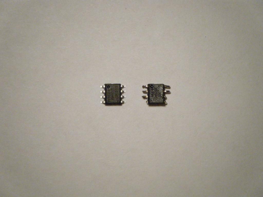
DS1307 RTC SO
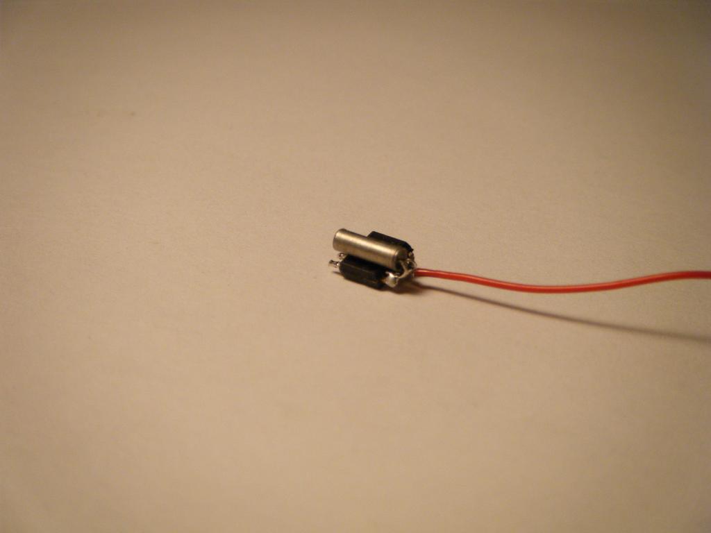
32,768kHz Crystal 12.5pF
3v lithium battery
Step 1: Straighten pins 1,2,3,7,8
Bend pins 4,5,6 slightly downward
Step 2: Solder the crystal across pins 1 & 2
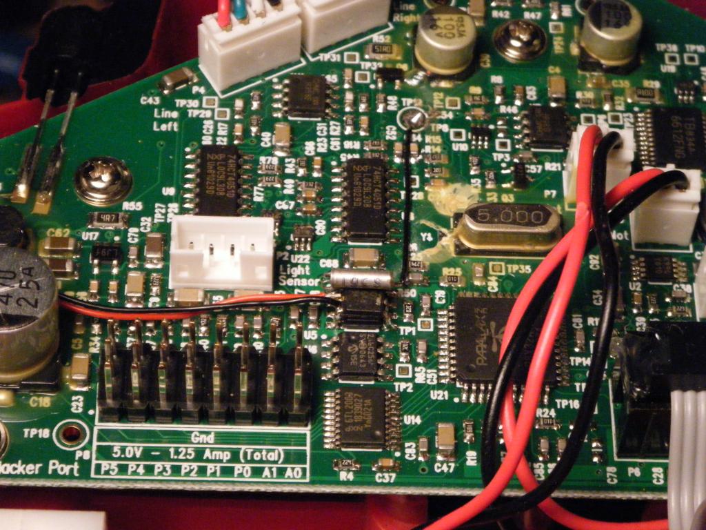
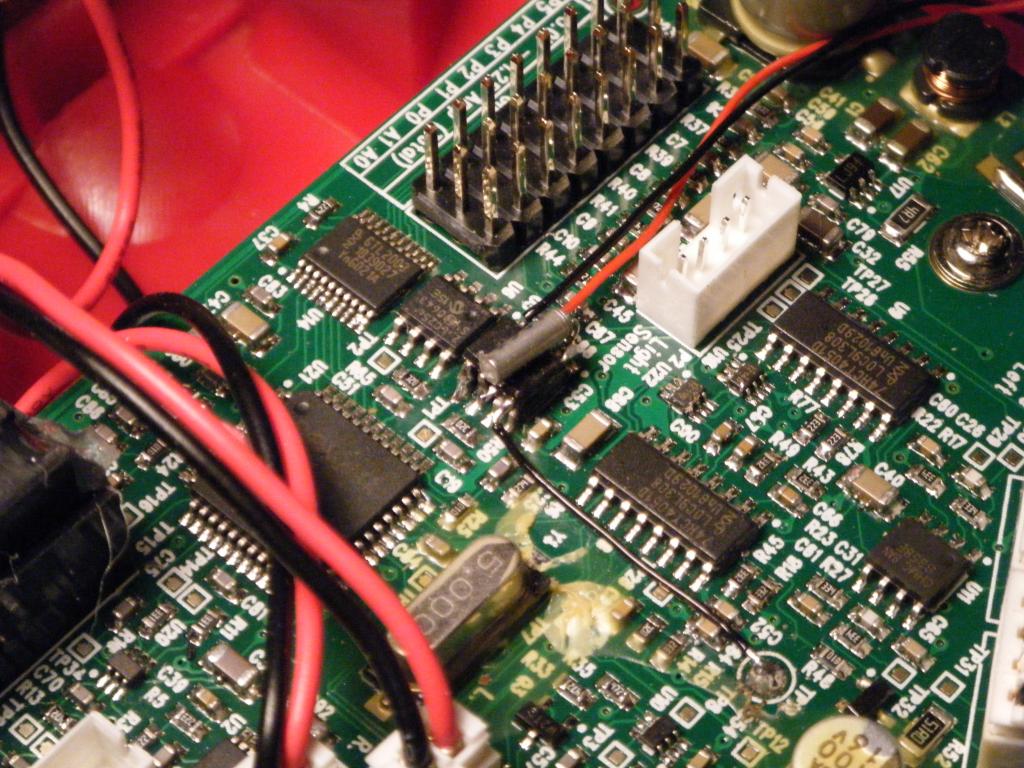
Step 3: Piggyback the DS1307 onto one of the EEPROMs of the S2
(I choose the forward one since it was easier to access when soldering the leads)
Carefuly solder pins 4,5,6
Step 4: Solder a short piece of wire from pin 8 to TP19 (5v) on the S2 black wire running forward in the photo ~1in long
Step 5: Solder a small 3v button battery across pin 3 (+) and pin 4 (gnd) I tucked the battery on the far left side of the S2 where
there is several small out of the way cubby holes
Step 6: Test it with the DS1307_RTCDemo program from the object exchange.
Next project is to get a pen lifter so I can write the time and date.


Comments
Why not incorporate a whiteboard eraser, too, while you're at it. Then you could have a continuously-running digital clock!
-Phil
I think for microcontrollers that support I2C the 1307 is the better chip. As you say no additional pins are consumed and odds are there's an interface library to hide the serial protocol. Although the BS2 can do I2C via bit banging, it uses up code space and is slower, so I would think the 1302 is a better choice. I've never run out of space on the BS2e and setting aside one bank for an I2C library that uses the scratch pad for inputs and outputs would make the 1307 useful there too.
BTW You have nerves of steel. I don't think I could take a soldering iron to a working surface mount board.
That would finally outdo this guy: http://www.ebaumsworld.com/flash/play/918898/
-Phil
I think H.G. Wells already had a patent on that.
I'll get right on it. Maybe I'll have it ready for the UPEC.