

What is a Microcontroller - Chapter 5 - Activity 2
 harshudeshpande
Posts: 5
harshudeshpande
Posts: 5
I wonder if someone could explain this to me. I have pasted a diagram from the book below. (I have added A and B markers)
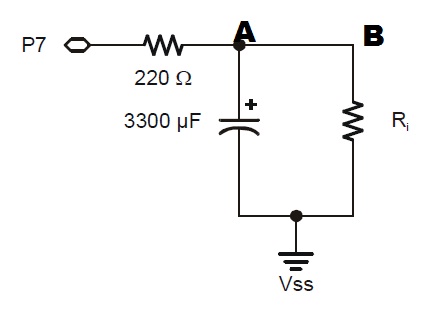
I understand the first part. High 7 makes the current flows throgh p7. As we add more and more resistance, more voltage flows through p7 - A - Capicitor + and the capacitor gets charged.
What I do not understand is the discharge part i.e when INPUT 7 command is executed.
The only way I could make sense of the program is is to think that the current flows from Capacitor positive to 220 Resistor to p7. But what I do not understand is how come P7 becomes negative charged? This is what I do not understand.
Thanks in advance for your time.

446 x 310 - 15K
Comments
Chapter 8 of the Propscope book will tell you more than you ever cared to know about RC Time circuits.