

PropKey: USB keychain Prop board (was ...toy...)
 pedward
Posts: 1,642
pedward
Posts: 1,642
If 'PropKey' isn't already taken, I was thinking of calling it that.
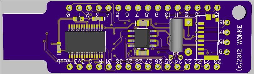
Yeah, that's a 300-mil DIP reset button, I've got like 29,000 of them. The LED is a 5mm bi-color unit, just what I had. The FT232RL and EEPROM are on the bottom. It runs off USB and plugs right into the port. 28 I/O pins are brought out, as is Vusb, Vdd, and Gnd. The FT232RL supplies a 6Mhz clock to the XI pin and also supplies 50ma for the chip.
I intend for this to be a key FOB kinda toy, for writing code and perhaps some light hacking. I have a couple more ideas, but it will take a PnP machine to make it economical.
My intention is to sell these or get them manufactured by somone else. I'm still thinking of putting a uSD connector on it, on the bottom side.
For "production" the M44 variant would be more appropriate because it leaves a lot more routing space, and of course an SMD reset and SMD leds.
EDIT: So here is the latest go at this idea, on the end is a Molex Micro SD socket. It's a card edge style, very compact.
The Micro SD socket is on P16-P19, I purposely left the P0-P15 contiguous on the one side of the key.
EDIT: Yet more changes. I took an inventory of components on hand and what I needed to order, changed a package and adjusted the layout slightly. I also replaced the slot with a hole, which will be easier
to make and more robust if it is actually hung from a keychain or lanyard.
The MicroSD socket is the small rectangle with the odd pads on the bottom side. The uSD card should extend over the end of the PropKey a little, so it's easy to grasp and remove.
I haven't wired the card detect pin, and I chose to wire the socket for standard SPI mode and not QSPI, to reduce pin usage.
This is the final revision I think, before I send the design off to have some prototype boards made. Turnaround should be 2 weeks.
I won't have any pricing available for a kit format until a later date. I may also sell bare boards if there is a demand.
EDIT: Here is the latest and greatest revision. The major difference is the addition of a crystal and adjustment of the power trace width.
I read about the caveats associated with the clock generator on the FT232, my main concern was poor stability, since the common use case for this board is in a USB socket.
I think I've beat the design to death and I'm ready to send it off to have a few boards made.
EDIT: This *is* the final design, all of the traces are routed how I want, the power traces are beefy (considering only 50ma is possible) and the 4 pin header is on .100 centers to the main 32 pin layout. I also added more labelling to the bottom, though many of the numbers are obscured by parts, between the top and bottom each pin is clearly labeled.

816 x 247 - 50K
812 x 236 - 46K
Comments
If there were such a product available, at a reasonable price point, I bet you'd see more articles using the Prop. I know I'd be able to pitch several, and I think there would be a built-in sales channel for the half-DIY crowd -- folks wanting to build, but not yet ready to jump in quite yet with both feet.
-- Gordon
I reckon that would fit in one of the usb cases Jazzed and I have discussed (Bud enclosures or New Age Enclosures)
@Gordon
The thing about uSD cards is that they can be "programmed" just by a laptop, or at worst a usb card reader from any computer store, using routines already present in the operating system (right click and "send to"). I'd argue that speaks to a wider crowd than those who can program I2C memories.
Having said that, I personally like the expansion possibilities of DIP8, and the possibilties of "autoscanning" i2c addresses to see what peripherals are attached. We already have Raymans 3AD accelerometer and Vanmunch's gyro. A RTC should be possible and with the new FTDI 'X' chips, I2C<>USB seems possible too.
The Prop is a .8mm pitch and the FT232RL is .65mm pitch, the passives are SOT-23, 0603, 0805, and 1208. The reset button is a nice tactile momentary PTH device. The soldering does present a challenge, but not a huge challenge.
EDIT: removed shots and put new ones at top.
Not what I'm talking about. The EEPROM is shipped to the customer pre-programmed. Two scenarios to consider:
Scenario 1: A mail order company stocks unprogrammed controller boards, useful for a number of kits. A customer buys a kit that has a certain functionality, and the mail order company drops in the appropriate pre-programmed EEPROM chip.
Scenario 2: A customer already has a controller board, and now wants to try it in a different kit. He or she orders the parts-only kit (no controller board this time -- saves them money), which comes with a pre-programmed 8-pin EEPROM. They pull out the old chip, and insert the new. The customer doesn't program anything.
Despite their ease of use, SD and uSD cards are more expensive than 8-pin DIPs, and card readers add to the cost of the controller board. The solution has to be as inexpensive as any other, or else why bother. (However, if there can be a reliable source of very low density uSD or SD cards that cost 40 or 50 cents in quantity, it's certainly an idea.)
The concept rests on a unique aspect of the Propeller, that its program is external. The majority of other controllers used for these types of kits all have internal flash, which means a lot of excess inventory waiting for a sale. Sellers of these ready-to-go kits may be more willing to try non-Arduino offerings if they can stock generic product that can be easily customized.
-- Gordon
best regards
Stefan
The FT201X series doesn't have DTR, so you can't do reset. I consider this a big omission, or did I miss something?
Apparently RTS reset is supported in the latest Propeller Tool. I'm also adding it to SimpleIDE.
The socket is about 5mm deep, which makes it easy to put towards the end of the board, without taking up too much space.
For people that are interested in kits, would you like a *complete* parts kit, or would you like to source some parts locally?
I've got a neat idea of how to provide a kit while making it very obvious which parts are what and to do a quick QA so no parts are left out.
I tried to make the layout spacious so that it could be soldered by hand and I haven't used any parts smaller than 0603. I made the pads for the SB socket bigger so they had some space to wick solder up from.
I'm in the same boat as User Name as far as parts are concerned.
Depending on what you end up selling these for, I may be interested in a couple.
Inside routing is usually expensive. I'd recommend doing a 4 or 5 large holes instead.
Bean
63 mils is what I'm prototyping with, but I measured a USB connector at .079. I was thinking that a creative way to resolve this is to get some thick plastic adhesive sheeting and adhere it to the back side of the USB connector end. This would make up the difference in thickness without costing a lot extra. I don't do a lot of PCBs, so I'm going through DorbotPDX to get these made, and like most, .063 is the standard. I think the shim idea is solid and innovative, which will keep prices down. I'd bet that it would be completely infeasible to offer these if I had to get .080 thick boards made up.
EDIT: I checked McMaster carr and they have .022 thick UHMW adhesive tape. This is perfect for the shim, since UHMW is very durable stuff and it will not abrade from being inserted. I tested a board here with some scotch tape and .022 is exactly the perfect thickness over the base to get a snug fit in USB ports.
Edit: I've got second thoughts about the kitting. If you've already got rolls and rolls of the right passives, perhaps you should include passive devices in the kits. Kludging a 1208 part into a 0603 footprint isn't worth saving a few pennies on the kit price.
Perhaps the only kitting option that makes sense is to offer them with or without Prop.
Honestly, the first layout without p28-p31 is cleaner than the revised layout. I also don't see much point in exposing the pins, since it's intended to plug directly into a USB port.
Please review the two layouts and give your thoughts.
While it's designed to plug into a USB port, end users may want to run it from a mains-to-usb plug pack, in which case powering from 1 source and programming from a second (prop plug) is advantageous.
You gain a second version of the board that can be programmed using a prop plug, saving the cost of the ftdi.
Finally, I2C (P28/29) is useful if you want to add an RTC (since you've got a uSD there already).
Here's what I did. http://forums.parallax.com/showthread.php?134602-Propeller-USB-Key I plan to re-spin it with the SSOP16 FTDI chip.
- the hole in the corner might be obscured by the uSD card when installed in the molex socket. Hard to tell without a line to see where the extent of the card ends.
- I reckon your design is a good chance of fitting in a ready made usb enclosure. However it may be a good idea to keep tracks as far as possible away from the 'shoulders' in case you need to file away some of the pcb to make your usb connector deep enough. eg the track that passes outside P0/P1 may be better to route in between P0/P1, and there is another track just outside the FTDI that may go inside the FTDI outline instead.
@jazzed,
The FT231X may be a better option as it has DTR for full compatibility. Its about 8c more in 100 off qtys, ie half the price of FT232RL. I only used the FT230X because I really couldn't spare the extra 1.3mm, however I will change to the FT231X when it goes on the other side.
I'm satisfied with the layout and will probably send the board off tomorrow.
Before You send it for production increase Power traces at least to dual thickness.
16 else more mil's
The FT232 can't generate the clock output until USB enumeration is complete. Ok so maybe that isn't as big a deal for your design that will mostly run plugged into a PC.
A few of us have been down that path at one stage or other to try to save an xtal. Separate xtal like you have now is a good idea
May I suggest you also add two extra pins in the P16-19, being 5V (or 3V3) and GND in the sequence V,GND,16,17,18,19. Why? Then your PropKey can look like a propplug to another prop board, and you can also supply 5V or 3V3 to this board. I have chosen to supply 5V and put cheap regulators on each of my modules.
If you do this, will the SD card interfere with these pins? If so, you could put them on the underside. I have 1x14 RA female (can be cut down) and 1x6 ST female (can be bent) if you require some.
Presume you are using DorkBox - you can put an overlay on the underside too! I suggest you label the I/O pins on the underside.
I'll probably send it off tomorrow, since all of the things that were in the back of my head are resolved and done.
I'm thinking that I'll offer a passives kit and full kit to start. I may even offer a hybrid kit that is partially assembled, with the hard parts mounted.