Line Frequency Detection / Measurement
 JonnyMac
Posts: 9,646
This should be easy -- I've done it before with the SX but with the Propeller I'm getting sporadic, unexpected results. What I would like to do is detect actual line frequency at start-up of my phase-dimmer object so that the same code will work world-wide. Again, should be easy.
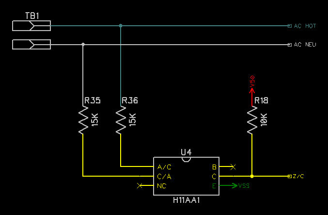
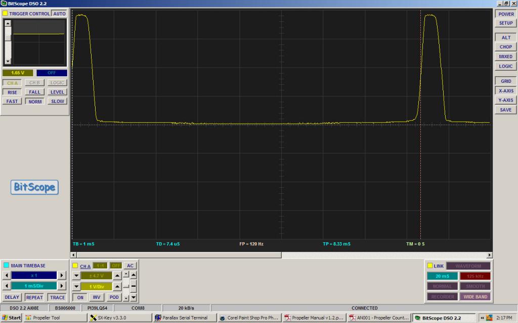
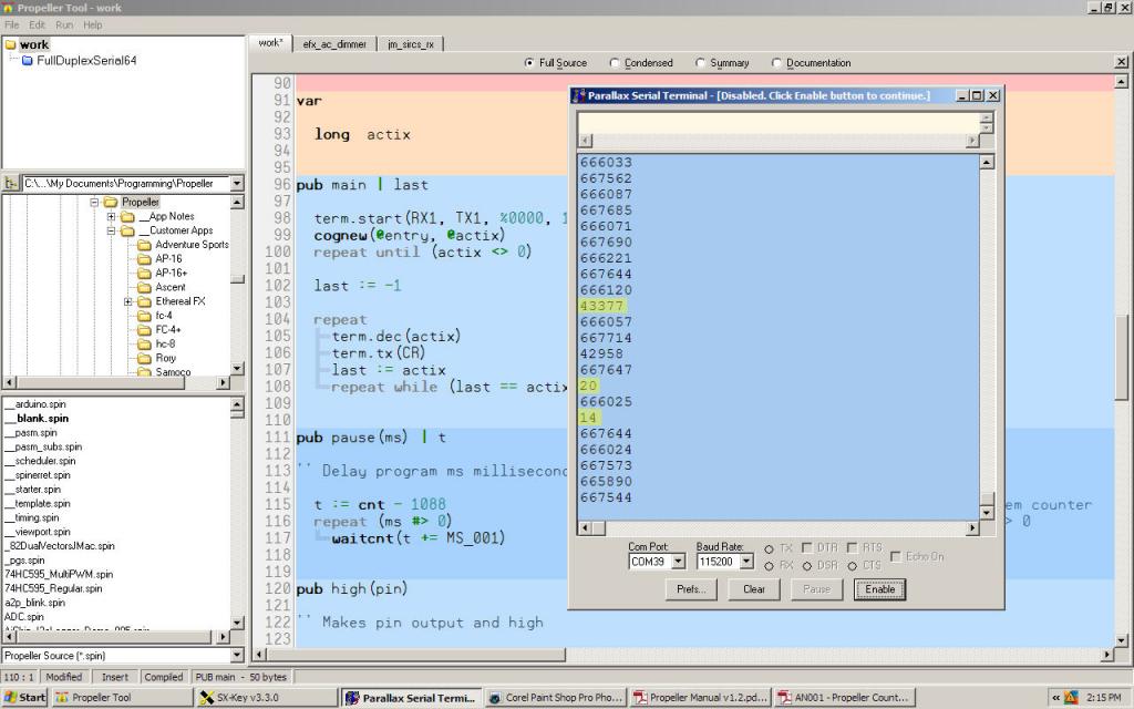
Pics show the circuit (no-brainer, everyone uses it), output from collector/pull-up junction, and wacky sporadic results in test program.
All thoughts and suggestions are appreciated.
Pics show the circuit (no-brainer, everyone uses it), output from collector/pull-up junction, and wacky sporadic results in test program.
All thoughts and suggestions are appreciated.
dat

                        org     0

entry                   mov     outa, #0
                        mov     dira, chdirs

loop                    waitpne zcmask, zcmask
                        waitpeq zcmask, zcmask
                        neg     period, cnt
                        waitpne zcmask, zcmask
                        waitpeq zcmask, zcmask
                        add     period, cnt
                        sub     period, #4

                        wrlong  period, par

                        rdlong  period, #0                      ' 1/4s delay
                        shr     period, #2
                        add     period, cnt
                        waitcnt period, #0
                        jmp     #loop


Comments
Seem like there may be some jitter on the signal when it crosses the threshold voltage. The SX may not have been fast enough to see the jitter, but the propeller is.
I'd try putting a couple millisecond delay between all the WAITPNE and WAITPEQ.
Just a guess...
Bean
P.S. Peter beat me to it...
-Phil
I agree with the other posts... also if you have any X-10 devices connected anywhere in the house they could be causing this sort of behavior. Even some of the 'Smart Grid" equipment that communicates during the zero crossing might potentially cause this sort of behavior. Have you scoped your mains, to see just how clean it is?
Am I fooling myself?
org     0

entry                   mov     outa, #0
                        mov     dira, chdirs

waitlo1                 mov     t1, #10
:loop                   test    zcmask, ina             wc
        if_c            jmp     #waitlo1
                        djnz    t1, #:loop

waithi1                 mov     t1, #10
:loop                   test    zcmask, ina             wc
        if_nc           jmp     #waithi1
                        djnz    t1, #:loop

                        neg     period, cnt

waitlo2                 mov     t1, #10
:loop                   test    zcmask, ina             wc
        if_c            jmp     #waitlo2
                        djnz    t1, #:loop

waithi2                 mov     t1, #10
:loop                   test    zcmask, ina             wc
        if_nc           jmp     #waithi2
                        djnz    t1, #:loop

                        add     period, cnt
                        sub     period, #4

                        wrlong  period, par

                        rdlong  period, #0
                        shr     period, #2
                        add     period, cnt
                        waitcnt period, #0
                        jmp     #waitlo1
Update: Well... that seems to have solved the problem and having installed this into my 4-channel AC dimmer object everything seems to be working well. Of course, I will spend a lot of time wringing it out before going public. The attached image is the board I'm working with (prototype of the EFX-TEK FC-4+).
Getting reliable Zero crossing on mains, is non trivial.
If you just want to make a Frequency decision, you can do a voting system, and discard the 'silly answers'
- ie a form of simple digital filtering.
If you want a more reliable phase-zero, for phase control, then you should make a bandpass filter, that removes spikes but does not phase shift too much at mains frequencies.
eg a series RC gives a phase-lead, and then a shunt RC gives a phase lag.
The toughest test situation is with three phase power, where another phase switches real power, right where you hope zero is.
A bit of ... what ?
I'd be cautious about those metal tabs just waving up in the air... anyone can slip..
Can you not get the devices in the TO220F or equivalent package ?
Looking at your board, I'm concerned about your mains isolation. It's not enough just to use optoisolators. You also have to maintain wide separations between conductors on the isolated vs. non-isolated sides of the circuit. In particular, you have a groundplane that surrounds the mains signals that really should not be there. Also, there's a diagonal trace emanating from the H11AA1 chip that runs perilously close to the hot side of the isolator and one of the 15K power resistors. In extreme cases, I've even seen slots cut into PCBs between the two sides to eliminate arc paths on the surface. That's probably not necessary here, but I mention it just to underline the importance of conductor separation distances.
Here's an article that might help:
-Phil
Filtering greatly helps, but then the rise-time is even slower.
The Schmidt trigger, along with filtering is the best solution.
Usually we use a hardware gate with Schmidt trigger gates.
However, with the Prop one can make a Schmidt trigger using 2 pins.
Forgive me but I don't remember what the obex is but it was describer here recently.
Basically one pin is the input and immediately the value is copied to a second output pin.
There is a resister from the output pin back to the input pin which changes the input
bias trip point. This greatly decreases the likelihood of false triggers.
Duane J
Yes that is certainly marginal, perhaps the Layout designer thought the resistors were isolation ?
8mm is the creepage distance some use, but certainly you should maximize within practical reason.
I'd also spread the 15K power resistors apart further; most are rated standing alone.
Except, the driving pin output is in phase with the sensing pin deliberately deviating from the trigger point, as opposed to, in the D-S AtoD, which is always attempting to drive toward the trigger point. I.e, NON-INVERTING output as opposed to INVERTING output.
Duane J
-Phil
Connect both outputs together and to a pullup resistor. Now the either opto is turned on all the time except for the very short interval between -0.6 and + 0.6. Works like a charm and is not sensitive to load or change.
As you can imagine, I am generating a lot of motor noise and the dimmer is rock solid.
DONT FORGET THE CURRENT LIMITING ON THE INPUT! (I know you wont but need to say it)
Lee
EDIT: Just noticed the PC814 and H11AA1 are similar. ...never mind.
Interesting is the CTR symmetry (skew) on these parts, and not all are equal. Some say 2:1, or even 3:1! and I see an Everlight 814A says 0.7<1< 1.3;
If this is only for AC frequency that does not matter, but for true zero cross as Phase Zero, you really need a known balance, and probably a Centre of Two edges design to take OptoGain out of eqn.
Least skew would be from a single LED driven from a bridge, but I've not found a vendor doing that.
My prize (by far) goes to Everlight EL814SATA 16c/500 at Mouser, and the best symmetry value.
I was assuming that, which is why the 15K is a little on the low side, and also why a better spec Opto coupler matters.
I'd flip to SMD couplers as they remove voltage from more of the board area, and likely have better long term availability.
The board shown is a prototype (we try to do those nicely, saving work later) and have identified some changes (in addition to the comments in this thread). I will try the EL814SATA for the next run.
Why not do it a different way, using the following, make an array, 1024 points, make an a/d out of a pin, sample the signal into the array, for say 1024 points... Set the sample rate so that you can easily resolve 50 or 60 hz, Maybe a 1000 Hz Sample rate... Then do an FFT, go and take the magnitude, Set a threshold, or search the array for the peak in the bins near 50 or 60 hz, and decide which is largest. The harmonics, and other parts of the signal are not that important, because you will effectively filter out the junk and will be able to decide what the line frequency is by looking at the fundemental and knowing about where to search. Right selection of sample rate, makes the index = the frequency. The fundemental of the line frequency will be clearly visible. You dont need to do this all the time, just once in the beginning. Perhaps you could verify that the line freq does not change much, either by running this more than once. I have not written this in Spin, but there are objects that do most of it. and the prop should be able to do this pretty easy. There is no need to really worry about real time, provided the sampling is done at a known fixed frequency. I dont think it matters much that that the signal is not a nice sine wave, the fundemental will show up just fine.
Just a thought, *** this would eliminate all the timing issues.
This is an interesting thing to read. Good luck with your project,
Regards,
Walt,
A design usually wants a (stable) Zero Cross time reference anyway to base the Phase calcs on.
So it is easier to work from this base.
I make a product that is targetted for 50/60 Hz and 110/240 volt operation around the world. It (still) happens to use an SX chip, but the same approach could be used for probably any micro.
The mains powers the micro directly through a "line rated" 1 uF capacitor into a power limiting 12 volt zenering transzorb, from which point it is series dioded to a 100 uF bulk storage capacitor that feeds a 5 volt regulator.
Beauty of this scheme is that the 1uF capacitor is a reactive limiter, and hence no heat is generated in dropping the 110/220 line voltage to the 12 volt zener.
Then I simply connect the hot side of the line through a couple of 1 meg resistors to a micro input pin as my phase reference. The input threshold is 2.5 volts, and the slew rate of the mains at that point is very fast, yielding wonderfully reliable results. On bootup, I first count and average the number of clocks between transitions on the phase input, and then adjust my master processor timing delay to get 128 time slots per half cycle, and sequence everything from that.
Works great.... thousands sold!
Cheers,
Peter (pjv)
No series surge resistor ? It may avoid any heat, but the power factor is lousy, and it will cost more to operate this over its life.
I guess if it is in kW dimmers, the control cost is in the noise floor, but for other applications, this does need care.
You also should provide a discharge path for the 1uF, if it is plug-able, otherwise it can sit hot waiting to bite someone...
We have used the VR37 series of high voltage resistors for this, but usually no less than 4M7, as you need to keep well clear of Earth-leakage tests of 250uA. Digikey shows 10M and 3M3 and 4M7 as stocked in tens of thousands.
Some designs use two VR37 in series, for better spike (lightning) protection.
I see the Prop specs +/- 1uA MAX Leakage, and Clamp max of 500uA in IO pins.