Shop OBEX P1 Docs P2 Docs Learn Events
Desperate for help for How to get P8X32A to read the GPS data. — Parallax Forums

Desperate for help for How to get P8X32A to read the GPS data.

tdp_projecttdp_project Posts: 2
edited 2012-03-29 12:11 in Accessories
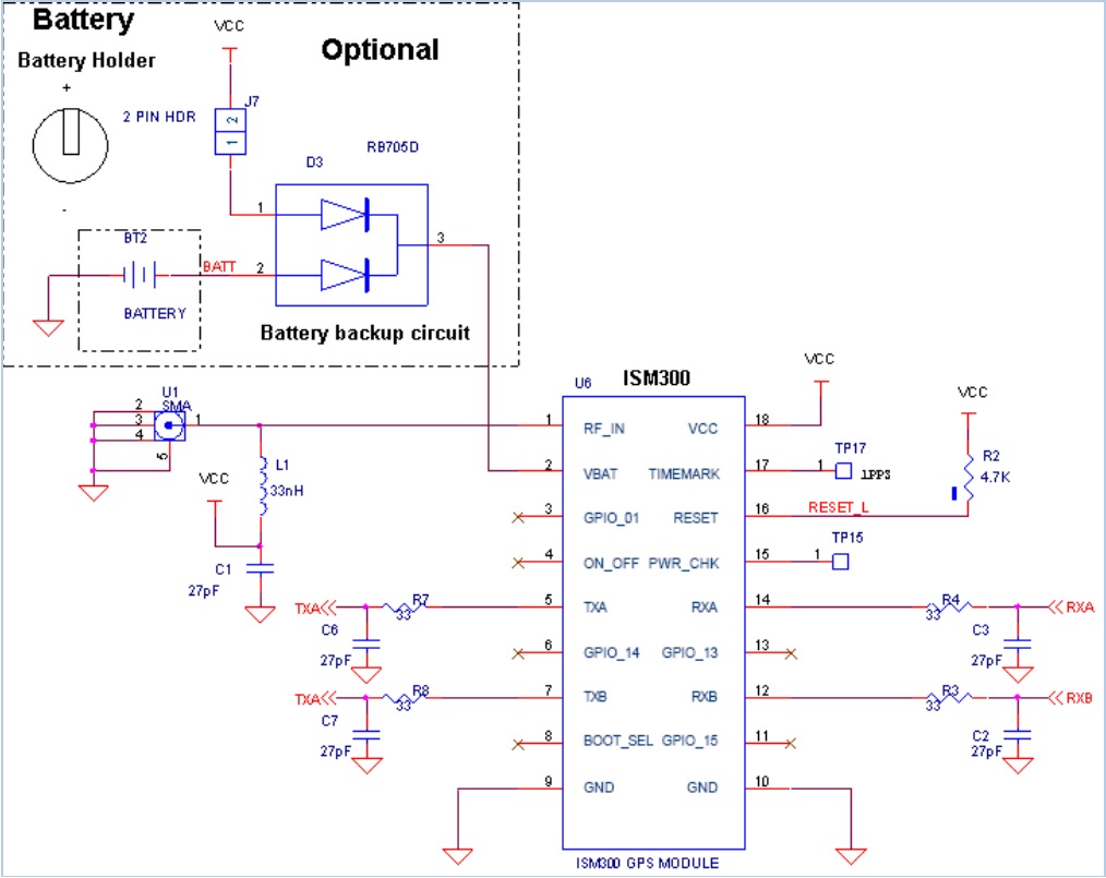
I'm currently working on a project that must require a GPS to incorporate with the microcontroller to read the output data from the GPS (time,longitude,latitude, direction, and speed). From the what I've known or told (there's no datasheet except for functional), just a simple transmitter (Tx) and receiver (Rx) connection to 2 i/o P8X32A pins is needed. I want the PST to display: time,longitude,latitude, direction, and speed. PLEASE help me with this, as how to connect it properly or what I should do!!!
I've attached a schematic of the GPS.

Here is sample code i'm working with (Am I using the right code?):
Gps config.jpg
GPS_to_VGA.zip
1014 x 805 - 129K

Comments

  • Mike GreenMike Green Posts: 23,101
    edited 2012-03-24 15:20
    To understand how to connect and program this, you have to have a datasheet that tells you what voltages the GPS unit requires and provides and what Baud it uses. Since the GPS has two serial ports, you'll need to know what each one does. You need to know what the GPS is sending and its format assuming that the GPS unit doesn't need any initialization from the Propeller. Only then does it make sense to hook the Propeller to it and put together a program.
  • kwinnkwinn Posts: 8,697
    edited 2012-03-24 15:24
    The code you have is for putting GPS data to a VGA display but I am not sure if it is for the ISM300 module. As far as connecting the unit to the Propeller you are correct that only two connections are needed but there is one CAUTION.

    IF THE ISM MODULE Vcc IS 5V YOU NEED A 3.3K RESISTOR BETWEEN THE ISM TX PIN AND THE PROP RX PIN.
    If it runs at 3.3V that resistor is not required. The ISM RX pin connects to the prop TX pin. You will also need to connect the Vss on both boards together.
  • tdp_projecttdp_project Posts: 2
    edited 2012-03-29 09:42
    Thanks, I really appreciate your help. The GPS operates at 3.3V with baud rate of 4800. TXa is in SiRF format and TXb is in NMEA format. Yes, you were right no not needing a 3.3K resistor. I've tried to connect TXa and TXb to the Propeller chip instead of 1 TX and 1 RX, and its seem to have an output. Do you guys know how to explain this?
  • LeonLeon Posts: 7,620
    edited 2012-03-29 10:11
    Some modules have TxD and RxD swapped, because of the difference between a DTE and a DCE. That caught me out once - my prototype PCB didn't work and I had to modify it.
  • WBA ConsultingWBA Consulting Posts: 2,933
    edited 2012-03-29 12:11
    Per the data you supplied, you should be able to connect TXb to pin 7 on the Propeller and use the code from Parallax Semiconductor AppNote 002 to verify that the GPS is working properly with the Propeller. From there, you can add direction and speed to the PST display by modifying the demo code.
Sign In or Register to comment.