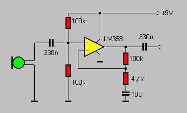
Propeller-Chip sound-input through a microphone suitable ciruit
 StefanL38
Posts: 2,292
Hi,
I want to build a supersimple sound triggered LED -thing
meaning a microphone is connected through a simple microphone-amplifier to an inputpin and whenever the music has a bass-beat
the mic-amp should output a voltage above theshold-voltage and otherwise below. Just to trigger the input-pin by the music-beats.
So low-noise linear amplifying is not nescessary.
I made a pre-test with this small circuit with no success.
Pretest means I connected the mic at input and headphones at the output of the circuit shown above.
First I used the resistor-values shown in the picture. (gives an amp-factor around 20 not much for a mic-amp.)
Then I tried a 1 MOhm instead of the 100k and 1k instead of the 4k7 resistors (giving an amp-factor of 1000 quite much for an OP-Amp)
When I touched the non-inverting input with my finger I can hear this typical 50 Hz humming. When I connect the mic I could not hear anything even
when bumping against the mic. The impedance of the mic is 1kOhm. I tested the mic with the soundcard-input and there it worked well.
So what's wrong about this circuit?
Is a suplly-voltage of 5V too low?
Does this circuit only work with a certain kind of microphone?
Is an OpAmp type LM358 not suitable for this application?
Do I have to use an OpAmp like a TL071?
Please can somebody guide me to a working circuit?
The Delta-Sigma-ADC will not work as I'm using a DIP40-Propeller-Chip.
Thank you very much in advance
best regards
Stefan
I want to build a supersimple sound triggered LED -thing
meaning a microphone is connected through a simple microphone-amplifier to an inputpin and whenever the music has a bass-beat
the mic-amp should output a voltage above theshold-voltage and otherwise below. Just to trigger the input-pin by the music-beats.
So low-noise linear amplifying is not nescessary.
I made a pre-test with this small circuit

Pretest means I connected the mic at input and headphones at the output of the circuit shown above.
First I used the resistor-values shown in the picture. (gives an amp-factor around 20 not much for a mic-amp.)
Then I tried a 1 MOhm instead of the 100k and 1k instead of the 4k7 resistors (giving an amp-factor of 1000 quite much for an OP-Amp)
When I touched the non-inverting input with my finger I can hear this typical 50 Hz humming. When I connect the mic I could not hear anything even
when bumping against the mic. The impedance of the mic is 1kOhm. I tested the mic with the soundcard-input and there it worked well.
So what's wrong about this circuit?
Is a suplly-voltage of 5V too low?
Does this circuit only work with a certain kind of microphone?
Is an OpAmp type LM358 not suitable for this application?
Do I have to use an OpAmp like a TL071?
Please can somebody guide me to a working circuit?
The Delta-Sigma-ADC will not work as I'm using a DIP40-Propeller-Chip.
Thank you very much in advance
best regards
Stefan


Comments
I've seen reports from people who have carefully soldered surface mount parts to DIP pins at the package edge for this sort of use.
Regarding the amplifier ... It's a voltage amplifier and makes a very very poor headphone driver. I'm not surprised that you couldn't hear the microphone. Others should be able to critique the circuit itself much better than I can.
thank you very much for answering.
Maybe I have to explain a bit more:
I can't keep the wires short to the DIP-package as I'm using a self soldered board which has current-limiting resistors between prop-chip and sockets.
The hardware looks like this:
IO-pin----150 Ohm
socket
bread-board-wire----breadboard----next beradboard-wire----Amp-circuit.
I guess this is really too much wiring for a delta-sigma-ADC. I'm using this hardware in a propeller-group at school where I'm working as a teacher.
So the only place where I can keep wires short is a microphone-amplifier.
best regards
Stefan
If you're using an electret mic, you need a DC bias (pull-up resistor in the upper (+) mic pin in your schematic) to power it. Your PC's mic input may provide such a bias. Your amplifier circuit, as shown, does not.
-Phil