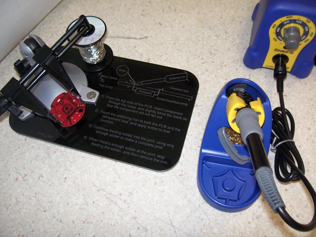
Learn how to solder @ the Parallax Expo!
So, as part of our UPCOMING EXPO!!! , we'll be hosting a "learn how to solder workshop" (LHTSW), along with a bunch of other cool things.
The LHTSW is centered around Phil's charming little S2 Blinkie Badge design, and is FREE here at the EXPO...(go tell it on the mountains, and ev verryyywhere)...

So, my challenge to all of you Expert Solder Jocky's out there is to proof the instructions and/or give some suggestions before we make a bunch of these!
Oh, and don't be afraid to say: "Matt, you're perfect in everything you do..."
(why, oh why, do I open myself up to these kinds of things???)
-Matt
The LHTSW is centered around Phil's charming little S2 Blinkie Badge design, and is FREE here at the EXPO...(go tell it on the mountains, and ev verryyywhere)...

So, my challenge to all of you Expert Solder Jocky's out there is to proof the instructions and/or give some suggestions before we make a bunch of these!
Oh, and don't be afraid to say: "Matt, you're perfect in everything you do..."
(why, oh why, do I open myself up to these kinds of things???)
-Matt


Comments
Robert
We'll just have to be sure that we'd have a qualified instructor @ those venues - Look's like YOU'RE IT Robert :thumb:
-Matt
I'll be glad to help teach anyone that wants to learn how to solder. I can explain how to solder both regular through hole components and even surface mount using ordinary tools.
Robert
Step 3 could probably be eliminated - it contains a little of Step 2 and 4 in the description. By the time I read from Step 2 to Step 4 I'd have fed a few feet of solder into the junction.
The concept is clean, useful and practical. Black acrylic seems to be the right material, too.
Ken Gracey
And then a detail of proper solder joints;
I would also recommend not putting the wheels on until last, just to avoid any accidental melting.
-Phil
The illustration you show has the solder on the wrong side of the component lead. It suggests heating the solder directly at the tip. Rich's illustration is more like what I'd do.
I think it's always a good idea to suggest a time limit, like no more than 4-5 seconds (or whatever). Beginners may not be aware the heat can't be applied indefinitely.
Finally, I am ambivalent about putting this on plastic, near where soldering is going on. Acrylic doesn't release horrible stuff when melting, but melted plastic takes quite a while to cool off, and I'd be concerned about people getting burned simply because they're not thinking -- you'd be AMAZED how often I try to clean off the excess as I use a hot melt glue gun. Talk about dumb!
It seems a bit unusual to use plastic for a solder station base. How about just making it a tent-fold sign or something? The base could be machine-cut aluminum. Maybe there's time to send it to an engraver to put the Parallax logo on it. Alternatively you could print this on paper or Mylar, and stick that on a metal base. Not a job for the in-house Laser Jocky, though.
-- Gordon
Also, what is the bottom and what is the top?
-Matt
My *personal* preference would be to do these on brushed aluminum (you may not wish to use your in-house laser for this, depending on its optics, or use CerMark), and then wipe-on/wipe-off black lacquer into the engraving. Rich's idea is great, though I think anodized aluminum will show its age after repeated use, and then it's more expensive to re-anodize. You can more easily clean up brushed aluminum with steel wool or brush and some wheel cleaner from Pep Boys, and re-apply the lacquer.
-- Gordon
Leaded solder or lead-free?
Easy or green?
I'm certain Parallax will go lead-free to be PC, although no one I know likes or uses that stuff. Not NASA, not no how!
You can get laserable anodized aluminum from BF Plastics:
It comes in 12 x 24" sheets, with thicknesses ranging up to 0.050". You'd have to shear or bandsaw them to usable size, and maybe adhere them to something heavier.
Here are some pre-cut sheets in smaller sizes:
-Phil
Chewbarka.com
They make (not re-sell) high quality anodized plates. What's really nice is that they anodize them after they are cut out so there are no sharp bare metal edges. They have many more sizes that what is listed on their website, you will probably need to call them to get the size you want.
It's orders of magnitude easier, and since the crowd will be complete newbies, they'll have a lot better chance of success. Plus, it's tough enough for a moderately experienced solder-jockey to get a joint that looks like the "good" example that'll be shown in the pics.
I'm not PC.
but, I'm not MAC either...
-Matt
I've used Front Panel Express for a recent project and was really impressed with the results. They have free software to layout the design of the panel. If you want an odd shape panel you can do it but you need to draw that in a different cad package and import it. Other than that you can do quite a bit. Blind holes (Front or rear), threaded, engraving, color inlay, etc, Quality is top notch.
You may be able to get material from them or have them do some of the fabrication.
http://www.frontpanelexpress.com/
Robert
I'd love to read what you wrote, but I don't see a link to the document. What am I missing?
Tony
No document, just the picture in the first post.