Coming Soon: Dual Relay Board Kit
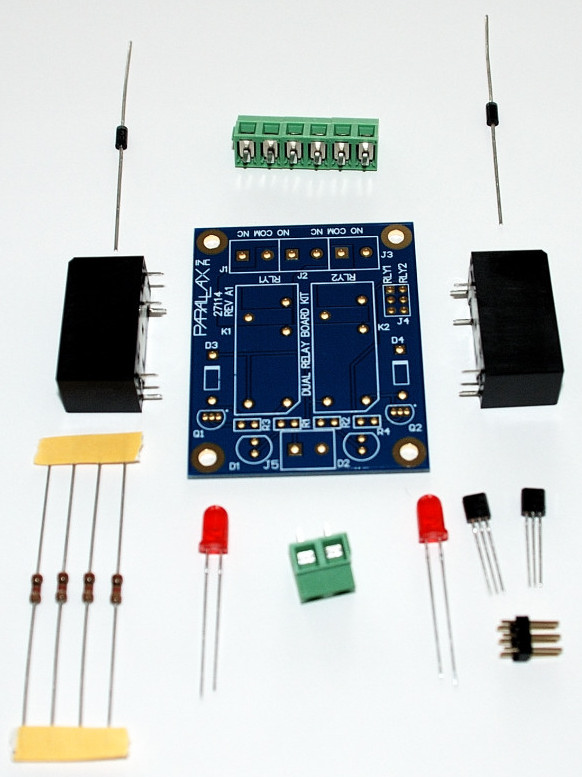
Parallax has a new product coming out based on feedback and requests from our customers. If you ever hada need to control 1 or 2 devices where a relay was required, the Dual Relay Board Kit is just what you need. The kit comes complete with the hardware shown below. Soldering required, but all through hole parts are used.

Once assembled the Dual Relay Board requires a 12V power supply for the relays and a signal and common ground to your BASIC Stamp Module, Propeller chip or other microcontroller output pin for each relay.

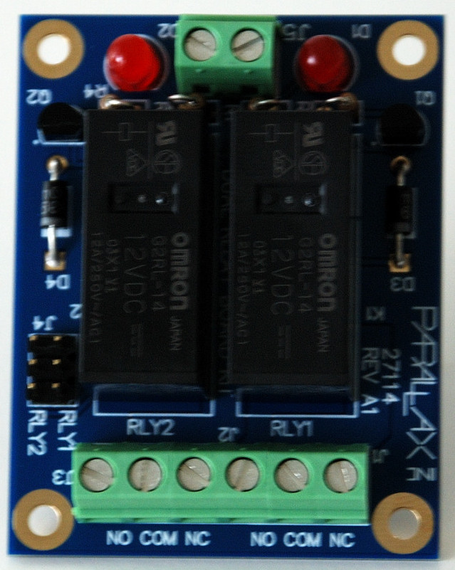
12V power for the relays is provided via the terminal block on the top of the board in the above photo. The LEDs indicate a relay is active (ON). The 2x3 header on the left provides ground and signal access to trigger each relay and can accept a standard servo cable such as those commonly used with many of our other accessories. The terminal block at the bottom provides COM, NO and NC connections to each Omron relay, capable of switching 12A @ 250VAC.
The drivers for the relays are simple 2N3904 transistors and can be activated by 3.3V and 5V. Diodes protect the transistors from back-emf and the board includes mounting holes. The dual relay board can also be controlled directly from the output of many sensors, such as our PIR sensor (#910-28027) or (#555-28027). If you have any questions, please reply. These should be available in mid-March.

Once assembled the Dual Relay Board requires a 12V power supply for the relays and a signal and common ground to your BASIC Stamp Module, Propeller chip or other microcontroller output pin for each relay.

12V power for the relays is provided via the terminal block on the top of the board in the above photo. The LEDs indicate a relay is active (ON). The 2x3 header on the left provides ground and signal access to trigger each relay and can accept a standard servo cable such as those commonly used with many of our other accessories. The terminal block at the bottom provides COM, NO and NC connections to each Omron relay, capable of switching 12A @ 250VAC.
The drivers for the relays are simple 2N3904 transistors and can be activated by 3.3V and 5V. Diodes protect the transistors from back-emf and the board includes mounting holes. The dual relay board can also be controlled directly from the output of many sensors, such as our PIR sensor (#910-28027) or (#555-28027). If you have any questions, please reply. These should be available in mid-March.


Comments
The datasheet for the 12A Omron Relay can be found on the product page on our website. See the section under contact ratings. Of course, when switching high-currect devices the power source should be fused before the relay board.
The spec sheet strongly implies that, under certain conditions, the relay can switch 12A. And it's not even a mercury-wetted type.
Impressive.
Kinda old school,huh?
I'm diggin' it!
What happens if I plug this 2X3 header into the servo header on the Prop Proto board or the PPDB?.
What happens to the five volts? or V_ext if I have that hooked up?.
-Tommy
Finally, Chris delivers a simple DIY solution. Thank you Chris! If I had time I'd be replacing the darned Tekmar control system in my home's boiler.
Ken Gracey
Erco... now =this= is old school!
I've always wanted one of these for some project.
(Yeah... probably watched too many old time monster movies.)
For example all the wiring in a home or business for a security system can act as an antenna. Or a nearby lightning strike can induce a high voltage in that wiring. If you have a transistor on the end of that wiring, Zappp! But if you isolate the wiring from the transistor using a good old fashioned mechanical relay, it becomes a tough reliable system.
The most "cool" relay I have ever seen is a stepper relay...
Tommy,
Since the relays require 12V to power them and that comes from the terminal block, the center pin on the servo headers is not connected. This frees you to connect the board to a BoE, PDB, PPDB, or any board that has a servo header and connects the ground and signal. This is the same way our HB-25 works, not connecting the servo voltage pin, since it isn't needed by the host controller.
The 12V relays do work with a little less voltage (see the datasheet on our website), and in a demo here on my bench I have provided power from the BoE VIN to the terminal block on the Relay Board. I also connected two servo conection cables from the BoE servo headers to the headers on the relay board (see red arrows in picture). You might notice I didn't connected the ground wire for power in this case since it is common with the BoE and the servo cables are already connecting ground.
The resistor chosen on the input of the driver transistors was chosen to provide enough base drive current from 3.3V or 5V systems based on the gain of the transistor and the current required to engage the relay. As Ken said, this is an easy solution to turn on a 120VAC lamp, motor, pump, etc. And of course you have two relays, so you can control two different devices while providing isolation. I hope this helps.
As a kit we'll keep the cost on this as low as we can.
I figured it was as simple as that, but I just wanted to be sure,
I almost had some trouble with the QTI sensor wiring harness. Good thing I double check my wiring...:)
-Tommy
Everyone should always feel free to ask question on products, especially when, as in this situation, the only information is available right here in the thread about the coming product. We will sometimes use feedback given at this stage to make minor changes to a product, however in this case I have sent a few samples out for direct feedback because it is such a simple product. All questions and feedback are appreciated.
PV Jr. - I love mine, indispensable. Definitely get a base mount (a 308 or 312) for it.
Holy moly!!! I didn't read through the dimension info and missed the physical size.
Now I get why it's spec'ed for mulitple amps switching current...
How will this compare to the EFX-TEK RC-4 Relay Control Board?
Your question is completely welcome and valid. The RC-4 uses Solid State Relays, whereas the Dual Relay Board Kit uses mechanical relays. Solid State Relays are great for switching AC loads especially when you want to minimize noise in the system. Some SSRs such as the Crydom relays used with the RC-4 have zero-crossing detectors to make this possible. However SSR relays are either AC or DC in their configuration and cannot switch both AC/DC circuits whereas a mechanical relay can. I'm not sure if there are SSRs for the RC-4 which can handle DC, but I doubt it. I believe the SSR current rating is also lower than the mechanical relays used on the Dual Relay Board Kit. If you have any additional questions, feel free to ask.
P
The mounting hole centers are 1.5" x 2.0"
Doc, very first post. Should be middle to end of this month. I think it mainly depends on how long to get the boards.
PJ,
I do have a base for it...sort of...I have the 335 Magnetic Base which I was going to use to attach it to my metal bench in the garage, but this unit is so handy for smaller, lighter work that I prefer to keep it inside, so I haven't even taken the 335 out of the packaging. And the PV Jr. hasn't yet needed a base for what I use it for.
When I need something bigger I use the Model 315 PCB Holder, equipped with a custom base by Matt Gilliland.
And speaking of the PV Jr. Ken Gracey has assembled 18 soldering stations for the Parallax Expo. Each station includes a PV Jr. I'll leave it to Ken to post the pictures of the kits since I do not have them.
UPDATE: Ken sent me the pictures of the PV Jr./Hakko Soldering Stations that will be set up for use at the Parallax Expo.
Is there going to be an optocoupler board?