IR LED & Receiver circuit
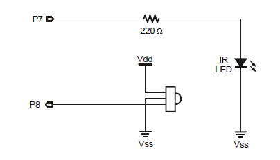
Hi, I am working in a class design group and we have lots of sensors and modules that we need to get all connected. To save ourselves from some headaches down the line we are hoping to make separate circuits, test that they work, and then connect them all to the Propellor Demo board running some master program.One of our modules is using an IR LED + Receiver to detect if someone has walked through a doorway. We purchased the IR LED (item code 350-00017) and LED Receiver (item code 350-00014). I found the following circuits included in the "Weekend Application Kit" pdf that is available on the IR Receiver product page:

I am ignoring the 220Ohm resistor and directly connecting the IR LED to a variable function-generator power supply and varying the input voltage with that. The kit states that the IR LED needs to be emitting about 40kHz which we have from the function generator (this is verified by an oscilloscope and we also turned down the frequency to something more humanly observable to verify the connections).
I have the receiver in a separate circuit, shown as above with Vdd = 5V (separate power supply from function generator). I am measuring voltage with a voltmeter from Vout(P8) to ground and read just under 5V. The kit also states that when the receiver detects the IR at 40kHz it will output a low voltage. However, the receiver will not change voltage except when the IR LED is first powering on or off. I will try to explain this better with the following scenarios:
Scenario 1: Receiver "on" / Vdd = 5V (no LED, beam broken)
Receiver Vout = ~5V (as expected)
Scenario 2: Vdd = 5V
Connect function generator to LED
Receiver Vout = ~0V for about 1.5-2 seconds, then hikes back up to ~5V
Scenario 3: Vdd = 5V
IR LED has been on for a while (few seconds) and is pointed directly at receiver, beam not broken
Receiver Vout = ~5V (should stay at 0V)
Because the only change in the receiver output voltage is when the LED is just turning on or off, we assumed that it was a frequency issue and tried varying the frequency but there was no change. Is there something obvious that we're missing here?


Comments
The IR can not be saved by just using a lower voltage, it needs a current limiter.
You have to use a 220 resistor for 3.3v and around 300ohm for 5v
Looking at the specs for my function generator unit it is not capable of that type of modulation. It would probably be best to just use code.