LED Nightlights
 Phil Pilgrim (PhiPi)
Posts: 23,514
The bulb in my bathroom nightlight burned out, so I went down to Safeway to buy a replacement. They had three bulbs for $2.99 and a complete LED nightlight for the same price. Certain that I would never have to purchase another bulb, I bought the LED unit and plugged it into the wall socket in the bathroom. It didn't take long to realize that this thing was way too dim and totally worthless for middle-of-the-night target acquisition, so I ended up replacing the bulb in the old fixture after all.
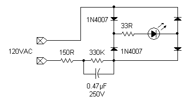
But I got to wondering how these tings were able to operate from 120VAC. Powering LEDs from mains voltage has come up in the forum before. So, in the interest of Science, I took the unit apart and traced the circuit. Here's what I found:

It uses full-wave rectification, with two of the diodes being high-voltage rectifiers; the other two, small glass devices. The main current limiter appears to be the paralleled RC combination. I have no idea what the purpose of the two additional resistors is, though.
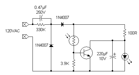
Emboldened by my discovery, I decided to analyze a hallway LED nightlight that I've had for some time. It's one of those units that comes on only when it gets dark. Here's what I found:

Again, the main current-limiting part is the paralleled RC element. Without the resistor, the rectification would appear to be a classic half-wave voltage doubler, which makes no sense in this app. I'm sure the parallel diode is only there to protect the rest of the circuitry from high reverse voltages. The role of the photoresistor is to turn on the transistor when the ambient light is bright, thus shorting out the LED so it doesn't turn on. This makes we wonder why the circuit was included at all, since it draws more current with the LED off than with it on. It's obviously just a sales gimmick.
-Phil
But I got to wondering how these tings were able to operate from 120VAC. Powering LEDs from mains voltage has come up in the forum before. So, in the interest of Science, I took the unit apart and traced the circuit. Here's what I found:
It uses full-wave rectification, with two of the diodes being high-voltage rectifiers; the other two, small glass devices. The main current limiter appears to be the paralleled RC combination. I have no idea what the purpose of the two additional resistors is, though.
Emboldened by my discovery, I decided to analyze a hallway LED nightlight that I've had for some time. It's one of those units that comes on only when it gets dark. Here's what I found:
Again, the main current-limiting part is the paralleled RC element. Without the resistor, the rectification would appear to be a classic half-wave voltage doubler, which makes no sense in this app. I'm sure the parallel diode is only there to protect the rest of the circuitry from high reverse voltages. The role of the photoresistor is to turn on the transistor when the ambient light is bright, thus shorting out the LED so it doesn't turn on. This makes we wonder why the circuit was included at all, since it draws more current with the LED off than with it on. It's obviously just a sales gimmick.
-Phil


Comments
The waste, it burns. Wasted components wasting energy by burning more when the thing is "off" so it will look like it's doing something.
Not only does the LED go out when the lights come on, it dims proportionately to the amount of light. Seems like alot of circuitry just for a night light...
I used LED strips which are much brighter than the LED nightlight. I'm running it off a 12ah battery (I'm testing various batteries). I just connected everything for testing. I have it triggered by motion sensors (five). It triggers entry into the foyer, on the first flight of steps, second flight of steps and hallway upstairs.
So it's not the voltage that kills an LED, but the current?
-Phil