Real Rotating Beacon
 xanadu
Posts: 3,347
I posted this in the Prop section instead of Projects section. Please feel free to move it, sorry.
It's Sunday. I should be out flying working on my PPL, but I'm stuck inside fixing email servers and fulfilling random, boring administrative tasks. The only thing that can save me from a boring afternoon stuck in the office is to build a real rotating beacon.
I have a simulated beacon on the same power strip as my soldering setup. I use the soldering station's power switch to turn it on and off but I also hit the power strip switch if I'm leaving for the night or long times. Either way when the beacon is off I don't wonder if anything is on. Anyway the simulated beacon just doesn't do it for me anymore. I want to build one with a single rotating red LED, for now.
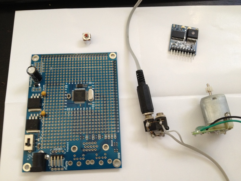
I have a fresh Prop Proto Board, continuous rotating servos, motor mind b enhanced motor controllers, a small DC motor (Roomba side brush motor), main Roomba motors, other small DC motors, (no steppers) and all the other electronics I think I'd need.
I was thinking of using a 3.5mm stereo jack, both sides as the coaxial connector to provide power. The female block side can be soldered to the Prop Proto and maybe just maybe the whole thing can sit on the Prop Proto with some standoffs.
Any thoughts or advice?


Comments
Here's some pics of the build - https://picasaweb.google.com/113085695335757647054/RotatingBeacon?authuser=0&authkey=Gv1sRgCPP1m8ee9orBmgE&feat=directlink
And a couple videos - https://www.youtube.com/watch?v=osrwcCItS-I
Next the MMBE and Prop.
'LED Rotating Beacon SPIN ' pin 07 on/off switch ' pin 08 beacon LED ' pin 12 motor relay PUB Beacon dira[7] := 0 dira[8] := 1 dira[12] := 1 repeat if ina[7] == 1 dira[8] := outa[8] := 1 dira[12] := outa[12] := 1 if ina[7] == 0 dira[8] := outa[8] := 0 dira[12] := outa[12] := 0Pretty cool project, but after looking at it, I think I may have done it differently, such as:
- I would have (4) LEDs mounted in an old time four sided flash bulb for camera usage. This would provide a reflective housing for the LEDs and it would provide more of a circular effect to the beacon.
- I would create a PCB with two circular wire traces and mount it to the motor face in between two standoffs on opposing sides.
- I would then attach two spring loaded motor brushes on opposing sides of the flash unit and mount the flash unit to the motor shaft.
The two spring loaded motor brushes would of course be in constant contact with the two circular wire traces on the PCB, with one brush providing power for the LEDs and the other providing ground.Bruce
EDIT: Another method to providing ground and power to the flash unit would be to salvage a slip ring, brush holder, and brushes from an old automotive alternator. This slip ring could be modified to mount to the motor shaft and the flash unit could be modified to fit the slip ring. At which point, the brush holder could be mounted to any stationary object, and the brushes could be terminated to the Proto Board.
If the motors shaft sticks out a liitle oppside side, I would try to use the motors shaft as gnd.
(Probably could do it even with a motor that only the the shaft on one side)
And then I only needed one circul/slipring.
For the power I will try hand etching some circular boards and also the slip ring system. I've never done either.
Placing 24 led in a very tight circle and go around in it with software, pwm so the transition looks smooth (eg micro stepping)
Perhaps a rotating mirror, tilted at 45 deg., above a stationary, vertically oriented led?
@