

Feedback Servo

Here's my latest shot at improving the standard servo: Feedback Servo
What I'm trying to do is easily retrieve the actual position of a servo.
(Gordon gave me this particular idea when he mentioned that servos go idle when not given an active pulse.)
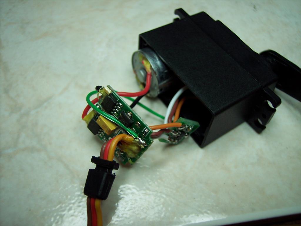
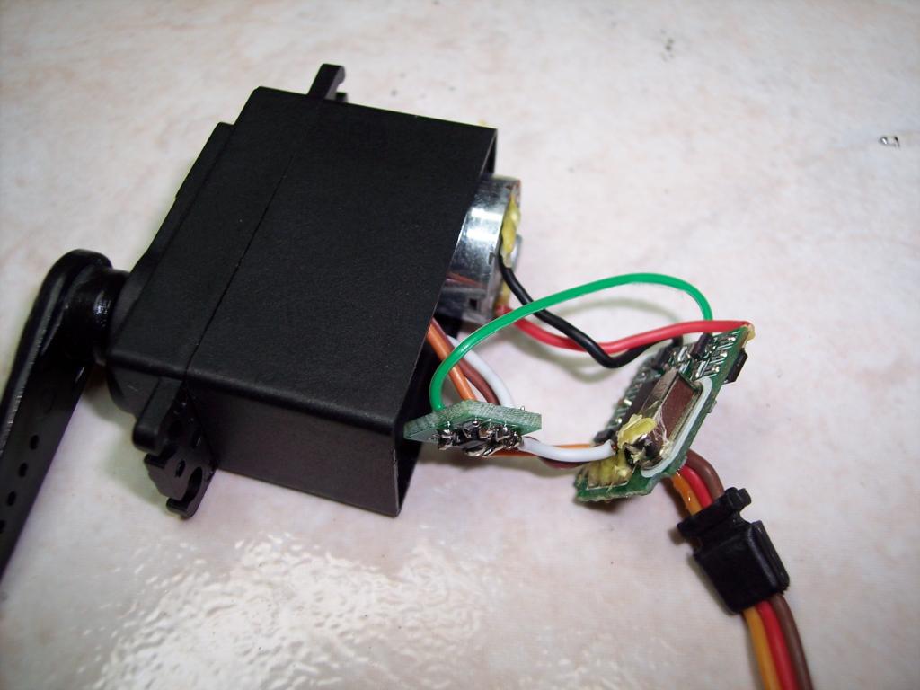
So, here's how it works. You just install a tiny opamp between the position POT and the servo input:


The opamp has a 1k resistor between it's output and the servo input.
So, in the usual case where the Propeller control pin is an output, the opamp has no affect since the Prop pin
sets the voltage.
But, if you set the Prop pin to be an input, now you can read the voltage of the servo's POT using a ADC connected to this pin.
Conveniently, the regular servo driver "Servo32v5.spin" sets the Prop pin to be an input when you give it a out of bounds value, not within 500 to 2500.
So, when you want to get the actual position of the servo, you just set the servo value to say "0" and then read the ADC.
I've just done some initial tests and I think this scheme is going to work nicely...
What I'm trying to do is easily retrieve the actual position of a servo.
(Gordon gave me this particular idea when he mentioned that servos go idle when not given an active pulse.)
So, here's how it works. You just install a tiny opamp between the position POT and the servo input:
The opamp has a 1k resistor between it's output and the servo input.
So, in the usual case where the Propeller control pin is an output, the opamp has no affect since the Prop pin
sets the voltage.
But, if you set the Prop pin to be an input, now you can read the voltage of the servo's POT using a ADC connected to this pin.
Conveniently, the regular servo driver "Servo32v5.spin" sets the Prop pin to be an input when you give it a out of bounds value, not within 500 to 2500.
So, when you want to get the actual position of the servo, you just set the servo value to say "0" and then read the ADC.
I've just done some initial tests and I think this scheme is going to work nicely...
Comments
-Phil
-- Gordon
It may require a small look-up table, worst case.
I think it will be very close to linear, but I know it won't be exactly because of the load from the input circuit to the servo...
The input circuit is a 4.7k resistor to the base of a transistor with emitter to ground.
My 1k output resistor was chosen to mostly force the desired voltage regardles of that circuit.
I could put in a 100 Ohm resistor and be more linear, but then the opamp circuit could draw more power than I'd like...
It also just occured to me that I could put in a little capacitor to ground and do RC time to get the position, instead of using an ADC.
But, I'm going to go with an ADC for now...
BTW: One main reason I'm doing this is to allow motion capture for a walking robot that I want to make...
I'll just go to "record mode" and monitor the servo positions while I move a limb manually, then go to "playback mode" and have it
repeat the motion...
"...there's an existing patent that covers sensing the current drawn from a servo to detect position and torque." - For a linear or rotary position sensor maybe as a form of a resolver, but to patent the concept on an existing product such as a hobby servo seems a bit of a stretch. That's almost like getting a patent on how to cut a straight line, and you pick the scissors you want to use.
"...Maybe that's why Parallax never commercialized the concept..." - My efforts were purely academic ... if an increase in servo sales were a result simply by awareness, then so be it.
Well known example: Samuel Fay made a small fortune on the paper clip, but the invention of serrated edges on the *unpatented* Gem clip (the one everyone is familiar with) made a whole lot more.
There's a company (not the aforementioned one) dealing with products in this category that has a surprising number of patents that you or I might think are obvious. Yet the Patent Office keeps awarded the patents.
-- Gordon
Wouldn't surprise me at all, now that I think about it.
But, even if was, I'd probably only get in trouble selling modified servos.
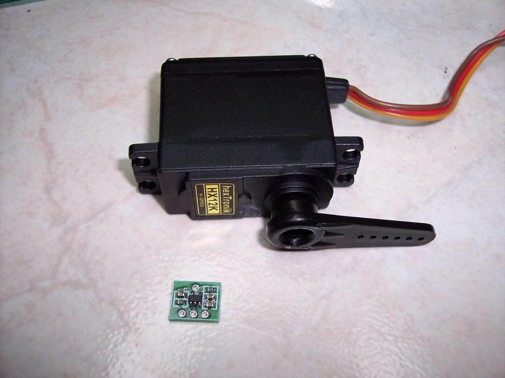
I might sell the little opamp PCBs, but I don't think I have the manpower to modify a bunch of servos here...
Anyway, I still have my original idea of reprogramming the PIC chip on the servo.
That's just a lot of work though. This is a lot easier...
Problem is that it's a bit less attractive and requires drilling through the servo case...
This way, it looks and acts exactly like a regular servo, but has a bonus feature of being able to read the actual position...
I wouldn't worry about it, and even if it were unless you're going to sell servos with this feature built-in you're just demonstrating an experimental concept. In any case, tapping off the pot in the servo has been mentioned for ages. The micro op-amp is very handy for this. I hate building those things on circuits. Always messy and huge.
-- Gordon
http://www.trossenrobotics.com/dynamixel-ax-12-robot-actuator.aspx
-- Gordon
Those things are dang cool. You can set the torque on those and read the torque they're experiencing. I've used a pair as a haptic feed back device. Of course you can also read the position of the AX-12. The software used in the humanoid made from AX-12s has you pose the robot and the software records the position for later play back.
I think this (position recording) is just what Rayman wants to do with his servos without spending $42 for each servo.
I want to make a robot with 4 servos on 4 legs and maybe a couple for head and tail...
Servo cost adds up fast...
Pretty good value for $8. I haven't used digital servos myself, but AFAIK you can set rotary limits and define ramping & top speed. Is there any position/torque/current feedback you can easily get from a digital servo as-is, without modification?
I wonder if that means they give you the source code for the PIC. I would love to have that...
Or, maybe they just change some values in the internal eeprom to make adjustments...
I started work on reprogramming the PIC myself, but it's a lot of work and not much fun...
From what I've read, one difference between digital and analog servos is the power applied when the servo is "off target". The power applied to the motor in an analog servo is proportional to the distance the servo is from its target position. A digital servo gives the motor full power at all distances from the target. This is one reason digital servos use more power than analog servos.
I've read that digital servos don't make good CR servos. I'm not sure why this claim was made. I've modified lots of digital servos as CR and they seem to work fine. I haven't done any side by side comparisons though.
http://www.sparkfun.com/products/9014
It looks like it is a drop in replacement for the existing board, but is controlled via I2C. This gives you position feedback because you can query the servo. It also works with a continuous rotation servo if you replace the pot with a hall effect sensor and magnet.
Also, I think you'd have to replace the 3-wire cable with a 4-wire one, right?
This little opamp board could cost $1 (or less), I think my digital, all-metal servo was $8, so the whole thing would be <$10
(I had a feeling this was going too well...)
I'm trying to decide how bad this is...
The problem is that at about the position of the minimum servo setting pulsewidth, 0.5 ms, the ouput of the opamp is 0.7 volts, just enough to turn on the input transistor....
So, there's a problem if you're not actively giving the servo pulses and manually move the servo around this point... The servo thinks it's getting a signal there and jumps away...
I suppose if it was getting active pulses and then for just a short time stopped to read the adc, it wouldn't be a problem...
But, I want to use this for motion capture with no active pulses...
I can make it work as long as you don't go even a hair below the 0.5ms point, but I'm not happy with this...
One possible solution maybe to add a 10k or so pullup resistor to the servo control pin.
It seems this would make it work over a wider range. There would still be glitch point, but it would occur well past the 0.5ms minimum width point...
Isn't 0.5ms outside this servo's normal range of motion. I thought these only have about a 90 degree range. I'd think a 0.5ms position wouldn't be a valid position. I don't think I measured the endpoint pulses on these but my impression was the endpoint was a lot closer to 1.0 ms than 0.5 ms.
I've wondered a bit more about the reprogramming the PIC option. Is there a PIC that's pin compatible that would let you add features?
I personally haven't programmed a PIC but I did learn enough about AVR programming to reprogram the Nordic fob SparkFun sells. I plan to replace the ATtiny24 with the pin compatible ATtiny84 so I can add some encryption and other features to the fob.
I wonder if something similar could be done with these servos? I don't know how much PICs cost but I'd think the price would be comparable to your opamp plus board. Of course there is the problem of removing the old chip.
I can think of all sorts of applications for a servo that would report its position. I'm very interested to see what you come up with.
I figured out how to reprogram the existing PIC, but it's just a lot of work to come up with a nice code... Right now, this is my last resort option...
0.5ms may be outside prefered range, I don't know. Beau's driver allows 500 to 2500 us by default...
This servo does behave a little funny at the 500 and 2500 limits... I wouldn't be surprised if these extremes are not recommended...
Anyway, I'd prefer there to be no glitches at all over the entire physically allowed range...
I'm still hoping the pull-up will solve this issue, but this approach may be in trouble if it doesn't...
But, now I see that Beau's servo driver isn't going to work for me...
Well, it does work, until you turn it off. Then, it lets go of the pin and the pullup pulls up the control pin and then the servo sometimes glitches...
Unfortunately, I think what I need is a modified servo driver that lets the control pin float up instead of forcing it up.
Then, while it's up, I need to do the ADC conversion to capture the position...
How are you turning it off?
It looks like if you set the servo out of range Beau's object (v7) makes the pin an input.
PUB Set(Pin, Width)|S_Width                                                     'Set Servo value
      S_Width := LowRange #> Width <# HighRange                                 'limit Width value
      Pin :=    0 #> Pin <# 31                                                  'limit Pin value between 0 and 31
      if RampFlag == 0
         ServoData[Pin] := (clkfreq / _1uS * S_Width)                           'calculate # of clocks for a specific Pulse Width
      else
         ServoData[Pin] := ((clkfreq / _1uS * S_Width)/SERVO#CoreSpeed)*SERVO#CoreSpeed

      ServoTarget[Pin] := ServoData[Pin]

      if S_Width==Width
         dira[Pin] := 1                                                         'set selected servo pin as an OUTPUT
     [B] else
         dira[Pin] := 0                                                         'set selected servo pin as an INPUT only if Width out of range
[/B]      ServoPinDirection := dira                                                 'Read I/O state of ALL pins
Have you tried setting the servo out of range as a way of turning it off?
The problem is when you move the servo around in this condition...
As the pin voltage crosses 0.7 volts, the servo jumps. It must think it sees a valid input for a millisecond and tries to move there...
It's all better with the 5k pullup. Only issue now is that I need to write a custom driver to use it in feedback mode.
It still works fine as a regular servo with Beau's code. But, feedback mode will need a special driver, I think.
Making the pin an input for an invalid setting is now a problem... The servo jumps when this happens because it thinks for a moment
that it should go all the way in one direction... So, my driver must keep the pin low for invalid settings...