

power issue. BS2 to #27931 CO gas sensor
 jorge_saldana
Posts: 8
jorge_saldana
Posts: 8
Hi guys,
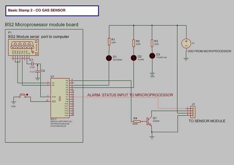
Now im working with a BS2 module. The programing and communications are running great. I use as programing base the same sample code of the CO Sensor gas module, and added what I need for my project. The issue im having rigth now is that; when i connect the HSW connection to the co module, it looks like is sinking too much current, the diodes start blinking with low intensity, and the debug window stats showing Smile on the instructions that are running. I tried isolating the HSW line with a 2N3904 switching transistor, but same occurs. Atteched is a drawing of the circuit and the modified code.
Gracias!
Jorge
Schematic:
' =========================================================================
'
' File...... CO Gas Sensor.bs2
' Purpose... Runs the CO Gas Sensor Module Heater
' Author.... Parallax, Inc.
' E-mail.... support@parallax.com
' Started... 02-09-2009
' Updated...
'
' {$STAMP BS2}
' {$PBASIC 2.5}
' {$PORT COM4}
'
' =========================================================================
'
[ Program Description ]
' This program runs the Gas Sensor Heater through two phases (voltages) as
' recommended by the manufacturer datasheet. The sensor should run for at
' least 10 minutes in clean air before any calibration is done.
' The first phase is the PURGE phase where the heater element is turned on
' at a full 5V. This clears the sensor and no checking for an alarm
' condition is done here. The DEBUG screen will count down the 60 seconds
' of this phase.
' The second phase is the SENSE phase where the heater element is run at
' ~1.4V for 90 seconds. It is during this phase that the sensor can be
' calibrated or that the sensor is checked for alarm conditions.
'
[ I/O Definitions ]
HSW PIN 0 ' Heater Switch Control
ALR PIN 1 ' Alarm Input Sense
SENSEled PIN 2 ' sense LED Display
ALRled PIN 3 ' Alarm LED Display
'
[ Variables ]
index VAR Word ' Counter Variable
sPin CON 16 'Serial Pin - P16, Programming port
Baud CON 84 'Baud mode for a rate of 9600, 8-N-1
'
[ Program Code ]
PAUSE 1000 'Allow data communications to stabilize
SEROUT sPin,Baud,[CR] 'Send a lone CR to ensure PLX-DAQ buffer is ready
SEROUT sPin,Baud,["CLEARDATA",CR] 'Clear all data columns (A-J) in Excel
SEROUT sPin,Baud,["RESETTIMER",CR] 'Reset Timer to 0
SEROUT sPin,Baud,["LABEL,Time,ALARM VALUE,STATUS",CR]
Main:
DO
HIGH ALRled 'Turn ALARM LED off
LOW SENSEled 'Turn SENSE LED ON(PURGE MODE)
HIGH HSW 'Turn Heater ON
index=60
FOR index = 60 TO 0 'Count Down 60 Seconds
SEROUT sPin,Baud,["MSG,PURGE MODE....",DEC index,CR] 'Purge Mode Alarm status is off(ALARM=0)
PAUSE 1000 ' 1 Second Pause
NEXT
index = 90 'Approximately 90 Seconds
DO
SEROUT sPin,Baud,["MSG,SENSE MODE....",DEC index,CR]
HIGH SENSEled 'Turn OFF SENSE LED
HIGH HSW ' Turn Heater ON
PAUSE 15 ' For 15 mS
INPUT HSW ' Turn Heater OFF
PAUSE 3 ' For 3 mS
index = index - 1 ' Decrement Counter
PAUSE 800
LOW SENSEled 'Turn SENSE LED ON
IF ALR = 1 THEN ' Check For Alarm Condition
SEROUT sPin,Baud,["DATA,TIME,","1",",","ALARM ON!!!! ",DEC index,CR]
LOW ALRled 'Turn ALARM LED ON
ELSE
HIGH ALRled 'TURN ALARM LED OFF
ENDIF
LOOP UNTIL index = 0 ' End Of Sense Mode Loop
LOOP

758 x 533 - 87K
Comments
To continue with this question, please start a new thread in the sensors forum. It is off topic. Moved
The heater resistance is 33 ohms, so with 5 volts it needs to draw 150 mA, which is above the limit for the regulator on the original BS2. The HSW input to the module controls a transistor on the module which turns the power on and off to the heater.
Thanks for the info. But still dosent working The co sensor module itself(like you said) have a driving circuit, but as soon as i connected the hsw line to the micro, the micro starts to works incorrecly. Because of that I added a secontary switching circuit with a 2N3904 , but the same happends. Noticed that the HSW is guiving about five volts(wich is normal in off condition). The micro is suppose to guive a GND(or lower voltage ) to activate the switch ,but that isnt happening. Any suggestions? Below are some pictures of the project box.
Secondary switching transistor.
View with the sensor module:
Project Box
The issue is that the Vdd voltage regulator on the Stamp cannot supply the current that is required by the sensor. The sensor needs 165 mA but the Stamp Vdd can only supply 50 mA. You will need to add a 5V regulator that has a higher current capability. It can power either the sensor alone or both the sensor and the Stamp. These sensors by their nature require quite a bit of current to provide the heat to drive a catalytic chemical reaction.
Thanks! I'll take that in consideration. Make the changes, and let you know.
Thanks again,
Jorge
Be sure the power supplies to the Stamp and sensor share a common ground.
Apart from that, you might be getting back some noise from the sensor, in which case a 10 uF (or so) cap across its power pins might help.
-- Gordon