

Solenoid Issue
 BrianZ
Posts: 28
BrianZ
Posts: 28
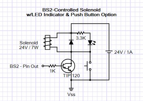
I am trying to use the BS2 to control a solenoid valve, and I'm having problems with this circuit...

My circuit is intended to control the valve primarily via the stamp, but with the option to use the pushbutton if needed to manually open the valve.
If I run my stamp program with or without the solenoid connected, the LED lights as expected in response to the on/off commands sent via the stamp output pin or push button switch; however, the solenoid never responds to either one. However, the solenoid works fine when connected directly to power.
Is there a problem with my circuit design, or am I possibly dealing with some other issue, like grounding, cable length, or thickness of the wiring? The wiring on the solenoid itself is fairly heavy gauge. When I first hooked it up and tested with just the LED and no solenoid, I didn't have the emitter pin of the TIP120 connected to Vss and the LED was always dimly lit, getting brighter when the signals were received from the stamp output, then after connecting to Vss, the LED no longer remained lit between signals, as expected. But now the solenoid doesn't respond, and I'm wondering if I have overlooked something. Unless I have a bad connection where the valve cable plugs into a in the jack on the project box that houses the stamp, switch, etc. I'm pretty sure I have checked all the wiring.
Any ideas about what the issue is or how to proceed with troubleshooting?
Thanks.
484 x 344 - 33K
Comments
Specs on the relay? Coil resistance in particular.
When you "...connected directly to power", what power? The same 24V source shown in the schematic?
The solenoid is rated at 24V and 6.9 watts. Here is the valve: http://www.valvestore.com/prodinfo.asp?number=42703 and there is a data sheet link on that page. It should only be drawing less than 300mA. I measured it's resistance at about 82 Ohms.
I am using a connector on the solenoid cable that is similar to the power connector at the the end of the 24V/1.25A supply. Both plug into jacks mounted on the plastic project box and wired inside the box where the stamp is. Yes, same 24V power supply - I can unplug solenoid and power supply plugs from the box, stick a short wire inside the center-positive holes of each connector, the touch their outside jacket contacts briefly together and the solenoid clicks open and closed. I also have a 9V/2A power supply that plugs into the box to power the stamp board. These supplies are the A/C adapter/converter type with a rectangular box in the middle of their cables. I measured their voltage outputs, which were both on target at 23.98V and 9.08V.
I guess you don't see any obvious problems with my circuit either then.
Disconnect the Stamp. What happens if you connect the input to the base to +5V? It should turn the driver on and actuate the solenoid.
You could also check the collector voltage with a DVM, when the solenoid is supposed to be actuated.
I had rechecked my voltages inside the box at the wires soldered to the jack terminals and they were all as expected; but one thing I had not done was checked voltage on the outside of the box inside the jack where the solenoid cable was plugged in. When I did, I found no voltage coming out and continuity testing showed it was the ground terminal to the shell of the connector socket that was not making contact, so either I had used the wrong terminal or it was faulty, so a little more soldering and everything is working fine now! It's a two-conductor jack, but there were three terminals, so apparently one is not connected to anything but provided for use with a switch. I thought I had checked that before, but maybe not.
In any case, I am relieved that it's not something in my circuit. I can now press the switch and the solenoid works fine, and I can run my Stamp program, and it will activate the solenoid according to the settings on my 8 input pins that I'm using to input the number of drops to release (1 or 2; and I can now hear the solenoid clicking once or twice - not tested with water yet), drop size (valve open 10 to 85ms), and time between drops (52-66ms). I'm using DIP switches to set the binary input values with a range that is targeted for photographing drops of water and drop collisions. The other half of my project box holds the HiViz Multitrigger circuit that I've been using to detect a falling drop with a photogate sensor and set off the camera and after an adjustable delay, the flash. Now I can move on to some actual testing.
Anyway, thanks again for all the helpful comments.
Oh - may I ask you to edit your first post and change the header to "solved"? It's always nice to see one resolved. :thumb:
Ok, I am relatively new at this, but I have managed to change my first post to Solved. I bet if this were made easier or more obvious then more people would do it. It takes a little digging by changing first to the "Advanced" editing mode, and then peaking into the Prefix options to find the choice "Solved".
Thanks again to all,
-Brian
PS: For anyone wanting just to draw a circuit like the one I posted here, but lacking the software tools, check out this browser-based tool, Vector Blocks:
http://bretm.home.comcast.net/~bretm/VectorBlocks/
It has its limitations but is handy for a making a quick illustration.