Shop OBEX P1 Docs P2 Docs Learn Events
IR LED Emitter/Detector Circuit — Parallax Forums

IR LED Emitter/Detector Circuit

rezrez Posts: 8
edited 2012-02-19 12:46 in Accessories
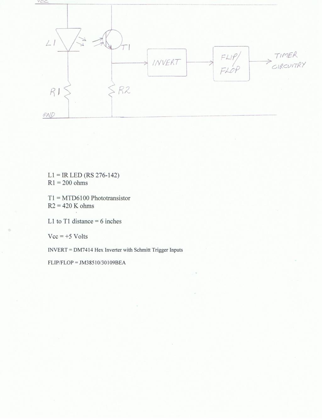
I told the Cubscouts I'd try to fix their Pinewood Derby Finish Line Timer. The part that is not working is the detection of the cars as they go by. The Timer circuitry is working okay. I've tried some different things but nothing I tried fixes the problem. The LED Emitter is working and the Detector decreases resistance when the IR LED comes on. Attached is the circuit information. I sure would appreciate some help. REZ
1024 x 1333 - 48K

Comments

  • LeonLeon Posts: 7,620
    edited 2012-02-12 14:29
    Was it working?

    See if the output of the inverter is triggering the flip-flop when the beam is interrupted. A scope will help, or a logic probe.
  • rezrez Posts: 8
    edited 2012-02-12 14:36
    Three of the four lanes were detecting the cars going by before a Cubscout father changed all the LEDs and Detectors on all four lanes out and threw away all the old parts. After he was done none of the four lanes would detect the cars going by. If I can get one to work I can fix the others.
  • rezrez Posts: 8
    edited 2012-02-12 14:41
    I don't have a scope or a logic probe.
  • ercoerco Posts: 20,255
    edited 2012-02-12 14:57
    You can get by with a multimeter if you know how to use it. Looking at your schematic, I was about to say you don't need the inverter, just swap your phototransistor & sweries resistor. But, that inverter brings a Schmitt trigger to the party, which is very handy. Use the meter to check all 4 lanes' LED output & sensor reading. Could be mechanical alignment, optical shielding, incorrect resistor on either side, bad LED, bad ptx.
  • rezrez Posts: 8
    edited 2012-02-12 15:03
    I'll give it a try. Are the resistor values okay?
  • ercoerco Posts: 20,255
    edited 2012-02-12 16:34
    Resistors look good to me electrically, though I like 1 Meg resistors on the ptx myself. I'd start testing by measuring the voltage at the ptx/resistor junction. Compare the voltage when the beam is blocked and unblocked, and make sure all lanes yield similar values. Then test the inverter outputs.
  • rezrez Posts: 8
    edited 2012-02-12 16:52
    I currently don't have a 1 Meg resistor, but I could make R2 about 750K for now. By the ptx I'm assuming you are referring to the Detector. I'm not familar with the term ptx.
  • tonyp12tonyp12 Posts: 1,950
    edited 2012-02-12 16:54
    Move the R2 to be above the sensor, a 10k value is OK. (or up 47k too)
    And move the trace that goes to mcu/flipflops to be above sensor too, but below resistor.
    You may not need the inverter in that case as a blocked beam will produce a 1.

    Remember, for a good reason most electronics is reversed,
    you supply voltage with 10k resistor and ground the trace to show a different state.
  • rezrez Posts: 8
    edited 2012-02-12 17:14
    I'll give it a try as nothing so far has changed anything.
  • kwinnkwinn Posts: 8,697
    edited 2012-02-12 19:32
    The first thing to check is the physical alignment of the emitter and sensor. This can be done by measuring the voltage across R2 while adjusting the emitter (L1) and the sensor (T1) positions. Adjust L1 first to get the maximum voltage across R2, then adjust T1. With a 5V supply the highest voltage you can get will be about 4.3 to 4.4 volts.

    If aligning the emitter/detector does not help try reducing the value of R1 to 120 or 100 ohms. The value of R1 looks suspiciously low to me. L1 is rated for a maximum continuous forward current of 150mA. An R1 resistance of 200 ohms will limit the current to about 22mA which may be too low.
  • jmgjmg Posts: 15,155
    edited 2012-02-12 20:44
    rez wrote: »
    ... before a Cubscout father changed all the LEDs and Detectors on all four lanes out and threw away all the old parts..

    Oops, oh dear...

    I think that Detector has no visible light filtering, so start in the gloom, with a short distance, and when you have that working, extend the length and ambient light, until it breaks again ...
  • rezrez Posts: 8
    edited 2012-02-19 10:20
    :smile: The track and timer work with the changes I made. Thanks for all the advise. The Cub Scouts will be pleased. Here is my solution based on all your comments. Thanks again.
    Lane Sensor Circuitry.jpg
    1024 x 745 - 40K
  • tonyp12tonyp12 Posts: 1,950
    edited 2012-02-19 11:23
    Maybe using a lower value than 1meg Ohm, 100k etc as you want fast rise time to time the cars to 1/1000 sec

    Could you just reverse the comporaters inputs to get rid of the inverter part, I think so.
  • rezrez Posts: 8
    edited 2012-02-19 12:46
    Thanks for your help. My project is complete.
Sign In or Register to comment.