

Basic Stamp Question - Button Switch Circuit
 BrianZ
Posts: 28
BrianZ
Posts: 28
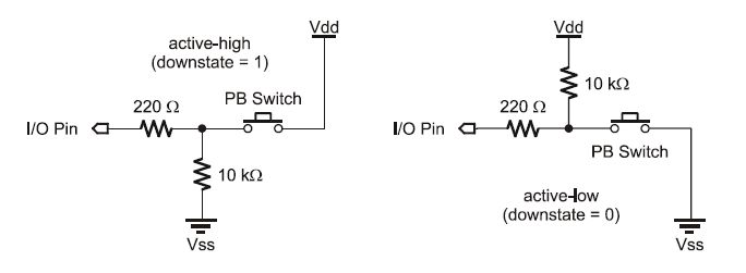
Ref: page 139 of the Basic Stamp 2.2 manual. (http://www.parallax.com/Portals/0/Downloads/docs/prod/stamps/web-BSM-v2.2.pdf)

My question is about the switch circuit illustrations shown for use with the Button command. Does the I/O pin sink any current or does it only see the voltage that is present on the other side of the 220 ohm resistor? I expect it is the latter, as I don't know how it would work otherwise, but wanted to make sure I understand how the Stamp pins handle this. More importantly, I know the BS2 is limited to 50mA per 8 I/O pins, and that would limit the number of switches if each was sinking 23 mA. If someone can confirm this for me, I'd appreciate it. Thanks.
My question is about the switch circuit illustrations shown for use with the Button command. Does the I/O pin sink any current or does it only see the voltage that is present on the other side of the 220 ohm resistor? I expect it is the latter, as I don't know how it would work otherwise, but wanted to make sure I understand how the Stamp pins handle this. More importantly, I know the BS2 is limited to 50mA per 8 I/O pins, and that would limit the number of switches if each was sinking 23 mA. If someone can confirm this for me, I'd appreciate it. Thanks.
684 x 251 - 16K
Comments