Need help with PhiPi's Goertzel_DTMF_Demo
 Wossname
Posts: 174
Regarding the Goertzel algorithm DTMF detection library (see the link in this post: http://forums.parallax.com/showthread.php?119568-Propeller-DTMF&p=876749&viewfull=1#post876749).
I've been wanting to add this feature to my current project but I'm having a bit of trouble converting the code to use an ADC chip instead of the Propeller Counter-based sigma/delta method that Phil used.
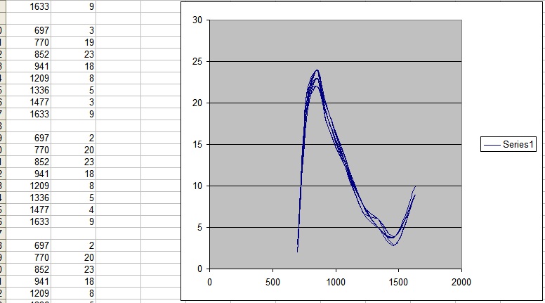
Basically all I've done is disable the Counter stuff and replaced the original "sample" subroutine with my own ADC code (which just reads a 10 bit value from the ADC chip on an SPI bus connection). The data being spat out of the serial port indicates that the algorithm seems to be functioning as a basic level but the actual values it produces are not a reflection of the actual audio I'm feeding in. It's definitely trying to give sensible output as the curve is a nice smooth polynomial and is very stable from one set of readings to the next (see the screenshot).
I suspect this is because there is a mismatch between what the algorithm expects to receive from the (old) ADC method and what it's actually receiving now I've mangled the code to get the dedicated ADC chip working. So the question is, how do I work out how to scale my 10-bit unsigned (0..1023) value to be compatible with Phil's algorithm.
That screenshot was generated from 697Hz+1209Hz (DTMF digit "1"), but the algorithm isn't reporting that. Clearly my ADC values need adjusting, but how I'm not sure.
My ADC spits out values between 480 and 540 (the audio is centred about +1.65 volts and has approx 200mv amplitude).
I realise this is hard to help with but any advice would be gratefully received.


Comments
If you'd like my help, please post all of your code, so I can see what you're doing.
-Phil
I can't really upload my code at the moment. There's a fair amount of in-development proprietary code surrounding your library. I'm looking into this Goertzel system as part of a proof-of-concept demo for work, (don't worry, the final product will be fully licence-compliant).
Can you tell me what range of values you expect your "sample" subroutine to return? If I can craft my ADC's values into that range then perhaps I'll have more luck.