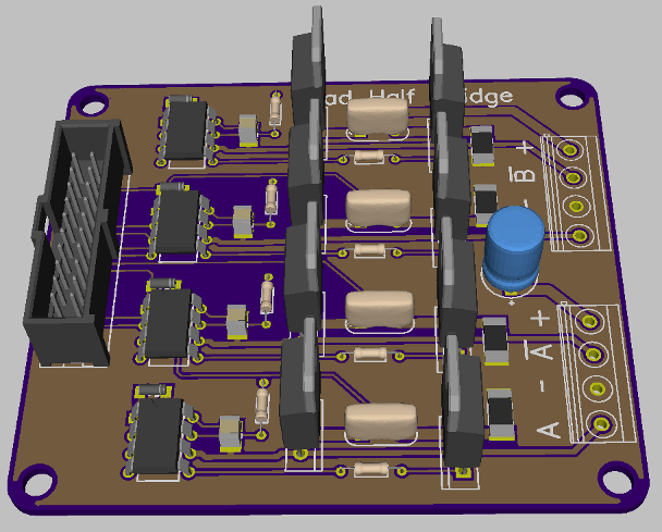
Quad Half Bridge driver board
 pedward
Posts: 1,642
I've been working on some stepper research and came up with a board design for a Quad Half Bridge.
Specs:
8A continuous rating per half bridge
.024 ohm 2W current sense chip resistor
48A 8.4 milliohm N-channet mosfets with ultra low 4-8nC gate charge
30V max voltage
IR2302 high side N-channel half bridge driver, runs off +5v
Phoenix contact 5.08mm MKDS series terminal blocks
To answer Phil's question first, the ground pour is only connected to the motor ground, but the logic and motor ground are connected by a single thin trace.
The board is rendered in the DorkbotPDX colors, probably how I'm going to have them fabbed.


Comments
Here is an optional motor connection method using a 4 conductor molex header and plug.
http://search.digikey.com/scripts/DkSearch/dksus.dll?x=0&y=0&lang=en&site=us&KeyWords=WM24036-ND
http://search.digikey.com/scripts/DkSearch/dksus.dll?WT.z_header=search_go&lang=en&site=us&keywords=WM18435-ND&x=0&y=0
Can be put in parallel to double that Amp rating. (waiting for pcbs from China, but will be ready soon)
Is there a need for 4-to-8 Amp stepper drivers?, as I may come up with a second high current version.