Shop OBEX P1 Docs P2 Docs Learn Events
Buttons — Parallax Forums

Buttons

bubby9534bubby9534 Posts: 36
edited 2012-02-02 15:41 in Accessories
Newbie electrical engineer here, wondering how this buttons panel works. Which wires corresponds to which buttons you can see the circuit printed on the board there but I can't seem to figure it out.
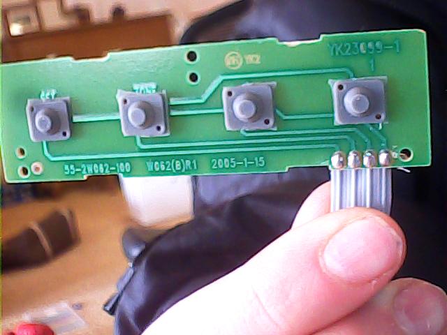
Picture 006.jpg
640 x 480 - 42K

Comments

  • LeonLeon Posts: 7,620
    edited 2012-02-02 11:50
    The right pin is common, and the left button is connected to the left pin, and so on.
  • Duane DegnDuane Degn Posts: 10,588
    edited 2012-02-02 12:15
    To add to what Leon said, I'd connect the common pin to ground and the other pins to Prop I/O pins (assuming a Prop as a uC). With the exception of the common pin, use pull-up resistors (10K) on the pins. This way the I/O pin sees a high value on the pin except when the button is pressed.

    SparkFun sells a wearable keypad that has similar (but a bit more complicated) layout. I made an object to use SparkFun's wearable keypad with a Propeller. There should be a link to it in post #2 of my index.
  • bubby9534bubby9534 Posts: 36
    edited 2012-02-02 14:30
    soooo I probably have this wrong but I would set it up like this?
    Picture 009.jpg
    640 x 480 - 48K
  • Duane DegnDuane Degn Posts: 10,588
    edited 2012-02-02 15:21
    It looks like you have the common wire connected to ground. Good.

    Each of the other wires should have a wire to connect them with a BS pin. It looks like your connecting through a resistor now. You don't want the resistor for this connection, just a wire.

    The resistors should connect to were the grey and black wires share a row on the breadboard. The other end of the resistors should be connected with 5V.

    Lets see if this schematic displays correctly.
                     5V
                      
                       10KΩ
        BS Pin  ─────┻──── button wire


    It looks like it worked.

    The BS pin will normally be high. Pressing the button will bring it low (since the common wire is connected to ground (without a resistor)).
  • bubby9534bubby9534 Posts: 36
    edited 2012-02-02 15:26
    Ah, thank you very much for clarifying. I'll post my project in the projects page soon!
  • Duane DegnDuane Degn Posts: 10,588
    edited 2012-02-02 15:33
    Great, I'll be watching for it.
  • Duane DegnDuane Degn Posts: 10,588
    edited 2012-02-02 15:41
    Bubby,

    I noticed the link in your signature takes me to a blank page.

    I was able to find your designs after looking a bit here:

    http://www.shapeways.com/hisdesign?user_id=104937&ug104937%5Brows%5D=10

    You might want to fix your signature link.
Sign In or Register to comment.