Shop OBEX P1 Docs P2 Docs Learn Events
ADC displays 512. Why? — Parallax Forums

ADC displays 512. Why?

lardomlardom Posts: 1,659
edited 2012-02-02 22:00 in Propeller 1
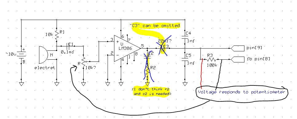
I want to display the signal magnitude from an electret microphone on the parallax serial terminal. The terminal only displays "512" which is the bit resolution. I constructed a circuit that worked properly with a 6v battery when I listened through an earphone. I connected the circuit to a prop and ran the ADC object. Once I saw I could only get "512" I measured the voltage across the feedback resistor which responded when I adjusted the potentiometer. I don't know enough about PASM to modify the code which seems to be the next place to check.
CON

   _clkmode       = xtal1 + pll8x
   _xinfreq       = 10_000_000

   INP_PIN        = 8           'Counter input pin for sigma-delta.
   FB_PIN         = 9           'Counter feedback pin for sigma-delta.
   ADC_INTERVAL   = 512         'Time interval over which to accumulate counts.

''=======[ External Object Reference ]============================================

{{ FullDuplexSerial is used to communicate with the user's PC. }}

OBJ

  sio   :       "FullDuplexSerial"

''=======[ Hub Variables ]========================================================

VAR

  long  value                   'ADC result variable.

''=======[ Public Methods... ]=====================================================

PUB  Start

{{ Initialize the serial I/O object and sigma-delta cog. Then repeatedly
   output the current ADC reading.
}}
  dira[1]~~

  sio.start(31, 30, 0, 9600)    'Start the serial I/O object.
  cognew(@adc_cog, @value)      'Start the sigma-delta cog.
  repeat                        'Repeat forever...
    sio.dec(value)              'Send the current ADC value,
    sio.tx(13)                  '  followed by a carriage return
    if value > 293
      outa[1]~~
      waitcnt(clkfreq + cnt)
      outa[1]~
''=======[ Assembly Code ]========================================================

DAT

{{ This code initializes, then continuously monitors the sigma-delta converter and
   writes the values acquired back to the hub.
}}

              org       0
adc_cog       mov       frqa,#1                 'Initialize frqa to count up by one.
              movi      ctra,#%0_01001_000      'Set ctra mode to positive w/feedback.
              movd      ctra,#FB_PIN            'Write fback pin number to dst field.
              movs      ctra,#INP_PIN           'Write input pin number to src field.
              mov       dira,fb_mask            'Make the feedback pin an output.
              mov       result_addr,par         'Save @value into result_addr.
          
main_loop     call      #adc                    'Get a new acquisition.
              wrlong    acc,result_addr         'Write result to hub.
              jmp       #main_loop              'Back for another.

adc           mov       time,cnt                'Get the current counter value.
              add       time,#16                'Add a little to get ahead.
              waitcnt   time,interval           'Sync to clock; add interval to time.
              neg       acc,phsa                'Negate phsa into result.
              waitcnt   time,#0                 'Wait for interval to pass.
              add       acc,phsa                'Add phsa into result.
adc_ret       ret

fb_mask       long      1 << FB_PIN             'Mask for feedback pin.
result_addr   long      0-0                     'Result address gets plugged in here.
interval      long      ADC_INTERVAL            'Acquisition time.

acc           res       1                       'General-purpose accumulator.
time          res       1                       'Time variable use for waitcnt.

Comments

  • Mike GreenMike Green Posts: 23,101
    edited 2012-02-02 10:11
    I believe R2 and C2 are needed for stability. There's probably a note in the LM386 datasheet on that. Look at the Demo Board schematic. It uses a 0.1uF capacitor between the two 1nF capacitors and the microphone output. You should have something like that for C3 at least. For that matter, why use the LM386 at all. The Demo Board does fine with just the microphone and bias resistor.
  • cavelambcavelamb Posts: 720
    edited 2012-02-02 10:34
    The LM386 is a single supply part - so the output has a DC offset.
    Without C3 to block that DC voltage the Propeller input pins will see the DC offset.
    If you are running it with a 6 volts supply, the -386 output probably shows about 3 volts with no input signal....
  • lardomlardom Posts: 1,659
    edited 2012-02-02 10:35
    Hi Mike. I'm not an expert at building amplifier circuits so I will move components around if needed. I removed "C3" because I thought "C1" (between the mic and the pot) could block DC without causing problems "C4" and "C5" where copied from the 'demo board' schematic. I'll replace those also.
    I'm not interested in the quality of the amplifier output so much as I just want to see the output value change.
  • lardomlardom Posts: 1,659
    edited 2012-02-02 10:49
    cavelamb, I forgot to consider that the LM386 would have its own DC component that would have to be removed. "C3" was 1mf originally and I removed it only after I listened to the audio with and without it. Does the capacitor size matter?
  • Phil Pilgrim (PhiPi)Phil Pilgrim (PhiPi) Posts: 23,514
    edited 2012-02-02 10:52
    You also need a resistor between the output of the amplifier and the input to the Propeller to limit the current and to provide a practical amount of gain with the 100K feedback resistor. Start with 150K, and if your readings are clipped, increase the resistance.

    If you've tried the circuit as drawn, your Propeller chip may already have been damaged. As noted above, it's better just to use the microphone circuit from the Demo Board, without the amplifier.

    -Phil
  • lardomlardom Posts: 1,659
    edited 2012-02-02 11:03
    OK Phil. (I used my Quickstart board!:innocent:) I don't mind buying another one. It's not the first time I've fried something...
    I used an amplifier so I could add sensitivity to the mic. I regard it as part of my education.
  • CircuitsoftCircuitsoft Posts: 1,166
    edited 2012-02-02 11:08
    You do need a /resistor/ where C3 is, and probably C3 too. Start with 100K and .1uF and gradually make it smaller to raise the level, but don't make it smaller than 1K.

    Really, though, you don't need the LM386 at all. The prop can detect some pretty fine inputs if you wire it up right.
    3.3v             3.3v
            &#9516;                &#9516;
            &#61628; 4.7K   1µF    &#61612;&#61613;&#61614;2.2nF
            &#9507;&#9472;&#9472;&#9472;&#9472;&#9472;&#9472;&#9472;&#9472;&#9472;&#61611;&#9472;&#9472;&#9472;&#9472;&#9472;&#9472;&#9547;&#9472;&#9472;&#9472;&#9472;&#9472;&#9472;&#9472;&#9472;&#9523;&#9472;&#9472;&#9472;&#9472;&#61610; APIN (9)
       Mic &#61567;&#61467;               &#61612;&#61613;&#61614;2.2nF  &#9492;&#9472;&#61629;&#61630;&#9472;&#61610; BPIN (8)
            &#61464;                &#61464;         10K
    
  • cavelambcavelamb Posts: 720
    edited 2012-02-02 14:21
    lardom wrote: »
    cavelamb, I forgot to consider that the LM386 would have its own DC component that would have to be removed. "C3" was 1mf originally and I removed it only after I listened to the audio with and without it. Does the capacitor size matter?

    It's been a while since I did much electronic design.
    I had to go look up how to bias a transistor switch the other day (blush).
    But I just noticed Phil's reply and realized you were running INTO the Prop pin, not out.
    I'm afraid there is a good chance that what he said is correct.
    Your circuit would likely put 5 volts into the pin, and that's not good.
    Try reading that pin without anything hooked up and see if it still responds correctly.
    If it doesn't work, there are 31 others...
  • CircuitsoftCircuitsoft Posts: 1,166
    edited 2012-02-02 14:24
    lardom wrote: »
    I used an amplifier so I could add sensitivity to the mic.
    You can do that by increasing the feedback resistance.
  • lardomlardom Posts: 1,659
    edited 2012-02-02 18:15
    @Circuitsoft, Placing a larger resistor on bpin[8] looks like the solution. I studied 'app-note 008' which explained how an op-amp operates. I don't always put '2+2' together. You can increase the gain by increasing the size of the feedback resistor.
    @Phil, I bought another Quickstart board. I am now aware of the 40ma source/sink limit on the Prop pins.
    @cavelamb,
    You can do that by increasing the feedback resistance.
    5v probably destroyed both pins. I'm new at amplifiers but 'lesson learned'.
  • CircuitsoftCircuitsoft Posts: 1,166
    edited 2012-02-02 18:22
    lardom wrote: »
    5v probably destroyed both pins. I'm new at amplifiers but 'lesson learned'.
    Hopefully, it destroyed only pin 9. The 10k should have protected pin 8. Try again on a different pair of I/O pins and see if it works. If so, you have a partially-functional board that's less of a loss if you break it,
  • lardomlardom Posts: 1,659
    edited 2012-02-02 22:00
    Circuitsoft, I see you used quote tags to display your schematic. I'm going to use that same method.
    The things I destroy most often are transistors, diodes and leds. I make sure I'm stocked up. I also have enough Props to keep me busy while I re order.
    I'm not disappointed. Even though I failed to get the range of values I wanted I the amplifier itself worked.
    Tomorrow I'll start working on the circuit again. I think I have enough new information to succeed this time. When I do I'll smile and be grateful to the people who helped me.
Sign In or Register to comment.