Please explain posedge detection with feedback
 lardom
Posts: 1,659
The real world is analog and knowing how to convert 'real world' analog to digital is a key concept. I won't have much success until I have a clear understanding of the conversion process.
I'm trying to figure out how to get some value other than 0 or 68-67 when running an ADC object. I've read that a pulse stream is generated and I believe the frequency of that pulse stream is proportional to the signal voltage.
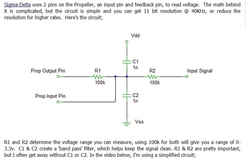
Can someone explain what feedback does and how the following circuit operates. There is a 10µf cap (not shown, copied from the parallax demo board) between R2 and the signal source which is an electret microphone. It is not amplified but I can hear my finger rubbing the element through my earphone.
I'm trying to figure out how to get some value other than 0 or 68-67 when running an ADC object. I've read that a pulse stream is generated and I believe the frequency of that pulse stream is proportional to the signal voltage.
Can someone explain what feedback does and how the following circuit operates.
CON

  _CLKMODE = XTAL1 + PLL16X
  _XINFREQ = 5_000_000

OBJ

  adc: "ADC"
  pst: "Parallax Serial Terminal"

VAR

  Long adcsample

PUB Main

  pst.Start(9600)
  adc.SigmaDelta(@adcsample )

  repeat
    pst.Dec(adcsample-32700)
    pst.newline
    waitcnt(clkfreq/2 + cnt)


Comments
Note: Some of my details may be slightly off, but that's the concept of how the SigmaDelta mode works.
Does that help?
A more thorough explanation can be found in Application note 008.
The way I typically describe Sigma delta ADC is this... Think of a CMOS inverter with it's output tied to the input. The resulting voltage on the output will be half of your supply voltage. Essentially your configuring the counter to be an inverter. The feedback resistor is tying the output to the input. Now, one slight difference in the software inverter is that there is a 1 clock cycle propagation delay of 12.5ns
Once the counter is setup and running as an inverter the natural bias is at 1/2 of Vdd .... without any external influence, you would expect the I/O to register a HIGH for 50% of the time while also regestering a LOW for 50% of the time, thus showing that the voltage is at 1/2 of Vdd.
Suppose that you 'persuaded' the pin externally to be LOW ... tied to ground... then the I/O would register a LOW 100% of the time and a HIGH 0% of the time. Likewise if you 'persuaded' the pin externally to be HIGH ... tied to Vdd. Then the I/O would register a HIGH 100% of the time and a LOW 0% of the time.
That's basically what's going on ... the second resistor is there to adjust the sensitivity or ratio of the input voltage to the 3.3V limit of the I/O. Sometimes you will see a capacitor to bias any DC when reading AC signals.
Another thing that is neat about a Sigma-Delta ADC is how you control the cycles... typically for an 8-bit ADC you sample for 256 clocks... a 12-Bit ADC 4096 clocks.
So for 8-Bit precision you can obtain a complete sample in 3.2us (80MHz clock * 256 clocks = 3.2us) ... A 12-Bit ADC takes 51.2us to obtain a sample (80MHz clock * 4096 clocks = 51.2us) ... Why is this important? Another neat trick... suppose you want to read a voltage, you might use an 8-bit ADC or a 12-Bit ADC to get the result, but then you have to convert it to something that is human readable. Why not save a step? By simply setting the Sigma-Delta Loop counter to 330 (assuming you have a 3.3Volt system) your output will be the voltage in 1/100ths units without any conversion afterwards... if you need more precision set the loop to 3300 for mV resolution.
The CMOS D flip-flop adds a clock which I'm thinking through at the moment. "Calibration", "reducing gain to less than unity" and "bit-precision" are also on my list of things to learn.
I'm examining puzzle pieces. The next step will be to assemble the puzzle.