Prop Waveform Design
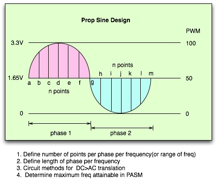
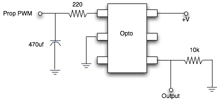
I have no real need for this, but just thinking out loud on methods and aspects of sine wave design using the Prop with no external DAC, no more than 2 pins used. This is strictly for fun in spare time. The goal, 20-15k(or 20K) for audio purposes, using no filtering of the audio signal. The idea is to use an opto to remove the PWM frequency, and leave only an average voltage on the output. I am not sure if the frequency range can be achieve with one set of filter caps on the front end of the opto. Ideally, among other things this would be midi-fied, ultimately poly.
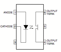
In other threads, filters can be a challenge to convert square waves. I was just experimenting on how a sine wave could be generated with minimal external hardware, by generating points along the curve to simulate a waveform. The current experiment uses PWM from 50-100, 100-50, 50-0, 0-50. The below example is using a circuit with a bi directional FET (Fairchild H11F1). The circuit does not show a method to convert the signal to a usable AC signal no DC offset, that is not important right now.
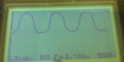
The example produces a crude very low frequency slow waveform, not practical for anything but testing the opto idea.
This works OK until you speed up the waitcnt value too high, so a fixed cap is not ideal for all frequencies.
My good scope is busted so this is a handheld version, pretty crappy view but it gets the idea over.
Any thoughts?
In other threads, filters can be a challenge to convert square waves. I was just experimenting on how a sine wave could be generated with minimal external hardware, by generating points along the curve to simulate a waveform. The current experiment uses PWM from 50-100, 100-50, 50-0, 0-50. The below example is using a circuit with a bi directional FET (Fairchild H11F1). The circuit does not show a method to convert the signal to a usable AC signal no DC offset, that is not important right now.
The example produces a crude very low frequency slow waveform, not practical for anything but testing the opto idea.
PUB Testwave| x     ' based on the cap size and divider circuit, the center point may not be 50, in this case is ~70.
  pwm1.start(13)
  pwm1.SetPeriod( 10000)
  repeat
    repeat x from 70 to 90 'linearly advance parameter from 0 to 100
      pwm1.SetDuty(x)
      waitcnt(500_000 + cnt)   'wait a little while before next update
    repeat x from 90 to 100 'linearly advance parameter from 0 to 100
      pwm1.SetDuty(x)
      waitcnt(2000_000 + cnt)   'wait a little while before next update
    repeat x from 100 to 90 'linearly advance parameter from 0 to 100
      pwm1.SetDuty(x)
      waitcnt(2000_000 + cnt)   'wait a little while before next update
    repeat x from 90 to 70 'linearly advance parameter from 0 to 100
      pwm1.SetDuty(x)
      waitcnt(500_000 + cnt)   'wait a little while before next update


    repeat x from 70 to 50 'linearly advance parameter from 0 to 100
      pwm1.SetDuty(x)
      waitcnt(500_000 + cnt)   'wait a little while before next update
    repeat x from 50 to 40 'linearly advance parameter from 0 to 100
      pwm1.SetDuty(x)
      waitcnt(3000_000 + cnt)   'wait a little while before next update
    repeat x from 40 to 50 'linearly advance parameter from 0 to 100
      pwm1.SetDuty(x)
      waitcnt(3000_000 + cnt)   'wait a little while before next update
    repeat x from 50 to 70 'linearly advance parameter from 0 to 100
      pwm1.SetDuty(x)
      waitcnt(500_000 + cnt)   'wait a little while before next update
This works OK until you speed up the waitcnt value too high, so a fixed cap is not ideal for all frequencies.
My good scope is busted so this is a handheld version, pretty crappy view but it gets the idea over.
Any thoughts?


