Propeller GUI touchscreen and full color display
 Dr_Acula
Posts: 5,484
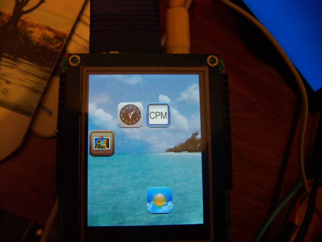
Version 1.0 of this little experiment in writing a Propeller GUI with graphics for the iphone generation!
See below for a screenshot.
Video of the touchscreen in action (sorry it is out of focus, the resolution is better represented in the photo)
Lots of experiments with different code, but essentially this needs an external ram for speed. The code is written for a Gadget Gangster Dracblade stack, and I'm hoping to have a batch of 30 boards available very soon.
The touchscreen is only $18 or so and easy to solder as it uses a standard 40 pin header.
Wide range of touchscreens here http://stores.ebay.com/Ego-China-Electronics
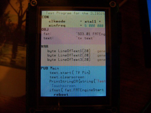
At the moment debugging is via a TV display but eventually this display should be able to have font libraries loaded into ram and so display debug messages on itself.
Ultimately this should be able to replace Kyedos where each icon runs a program instead of having to type in the name of the program.
I've been working on the problem of needing to use proprietory file formats. The background display is a standard .raw format (RGB) which most graphics programs should be able to output.
The icons start off life as a .png format and are converted to a RGBA format .icn with one long per pixel. This is similar to .raw but with a transparency byte, and there is some vb.net code to convert icons, and also a little Spin function to do this as well. The package contains the .png and .icn files as well as a background .raw file.


Comments
Good work Dr_Acula
Again, my apologies for the focus - it is the way my camera works and if you zoom in further there are moire effects between the pixels of the display and the pixels in the camera. So it is better to zoom out a bit and have it a bit out of focus.
Next we need some fonts for this display - I am working with taking the output from this program http://www.angelcode.com/products/bmfont/ and converting it into ILI9325 "two byte per pixel" format so characters can be loaded as quickly as possible.
-Phil
You have definitely captured my attention with this one. I will stay tuned.
Bruce
Brilliant!
I am using this program http://www.angelcode.com/products/bmfont/ and there is a description of how to create a file in the spin program.
Essentially, pick a font and it creates two files - a 256x256 .tga file, and a lookup table. I'm trying to keep to the philosophy of not needing intermediate programs too much, but in this case I do need to run this through paint shop pro, to i) take a negative of the image so it is black text on white background, and ii) to save it as a .raw file.
But having done that, copy the .raw and the .fnt files to the sd card and spin takes care of the rest.
So this is Arial 30 point and you can see on the screenshot of the .raw file if you zoom in then there is gray smoothing at the edges. This makes it look really good on the display and even with glasses it has hard to see the individual pixels.
I've got a couple of tiny bugs to iron out:
1) The space character does not seem to be created with the proper width, so I might need a manual fudge factor on that one.
2) The .fnt file starts the data at a different location depending on the length of the file name, so I need to decode the binary file further and work out how the data is being stored.
Arial is a variable width font, just to show it can be done. I did some initial testing with the Parallax font in 16 points so there are still some comments scattered through the code for that.
The calling routine in Spin is
ILIstr(string("Hello World!"),50,100)where 50,100 are the x and y coordinates on the screen.
At the moment the screen is in portrait mode, and if it is converted to landscape mode the font would need to be reprocessed with a slightly different spin routine.
I solved the "space" problem. I read the instructions *grin*
There is another variable stored in the font lookup table called 'xadvance' which shows how many pixels to move for that character. This is a printout of the first few ascii characters for Arial, which is a variable width font. 'xadvance' is variable. Underneath that is Courier New, which is a fixed width font and 'xadvance' is the same for each character.
It only takes a few minutes to create each font and copy to an SD card so the propeller can now have as many fonts as you desire.
I've also realised that doing a 'negative' in paint shop is not necessary - it is easy enough in spin.
Courier
Got black and white fonts working - can do any font at any size and also fixed and variable width fonts.
Now a few tweaks to do color, and also to rotate the font 90 degrees when the screen is in landscape mode.
How much of this might be possible at 8bit without the memory addition? I'm working on a similar project using a type .bat file to control things like opening files and user input. Like DOS the program would open the .bat file and act on it using commands for the display/touchscreen.
Jeff
Good question - I was thinking about that very question this morning. I think Kye's sd driver could be fast enough if you read blocks of data rather than individual bytes. Essentially, for each character, open the entire font file, jump quickly to the right part, read the block of pixel data in 512 byte blocks, then close the file.
So the challenge is to design a font protocol that is optimised for block reads. Get the ascii value, jump to data for that character with a simple multiply that can be done with a bitshift. Then get the x,y, offset, width etc. Precalculate the size = height*width so don't have to do that each time. Then jump to the pixel data.
If it works with no external memory it means you just need a gadget gangster motherboard, and a board for the touchscreen (these touchscreen boards come with an SD socket on them as well).
I shall try some code out in the next few days.
This is one of the most interesting and productive Propeller projects that I have seen since I have been a member. You have my vote for most interesting project. Those fonts look good.
Bruce
The GUI now has 'gestures'. Fingers swipes for scrolling through your photo album.
(After the third photo the finger swish is to the left to scroll back, but I must say this isn't obvious unless you watch it closely)
PUB TouchSwish | xval,oldxval,difference,average ' returns average +ve or -ve     ' did finger move left or right?
      oldxval := 255' for startup
      average := 0
      repeat until (average > 30) or (average < -30)
        ' possibly add a decay function here for average
        delay.pause1ms(50)
        xval := TouchValue & 255                        ' decode xval 0-100%
        if xval == 255                                  ' not touched
          oldxval := 255                                ' reset oldxval as well
        else
          if oldxval <>255                                ' discard the first reading as the screen is touched
            difference := xval - oldxval
            'printdecimal(xval)
            'printdecimal(difference)
            average := average + difference             '
            'printdecimal(average)
            'crlf
          oldxval := xval                                 ' store for next time
      result := average                                 ' return negative or positive value
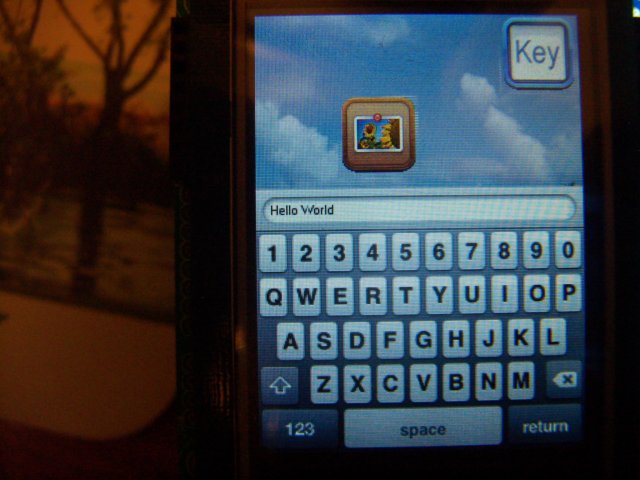
Now I think we need a touchpad keyboard...
I would say that I was talking about the cat, but I am sure you would know I was lying
Open a FAT file ... do something ... read/write to virtual memory ... continue do something on the opened file ...
The virtual memory has 4 slots, which means that 4 sectors of the swap-file (it can even be 4 different swap-files) are mirrored in HUB-RAM.
How does it help with your problem?
Instead of having tons of files for a font you can simply place the character data in this swap-file.
It's also good for storing background images or the button-images.
In my CogOS I even store all strings like error-messages, status messages, help-pages and stuff like that in this swap-file.
Addidionally I merried my graphics-display-driver with FSRW (that's why I use an older version which has some free COG-RAM), which means that the low level-driver takes over the graphics-display-bus.
So, when loading an image the display-driver prepares the display (for example setting a window) and then let's the FSRW pump the data directly to the display.
If you are interested I can search for old threads and/or provide my latest sources.
I have been thinking about ways of speeding up data transfer to these displays. The data can come from an SD card or an external ram chip.
These displays take some complicated instructions to set everything up, eg the window you want to send data to. But moving the data is very simple - there are 16 input lines, and you just toggle the write pin high and low and keep updating those 16 lines.
It leads to thinking about a completely different PCB layout.
Consider - with a touchscreen display you don't need a mouse or a VGA display or a TV display. Maybe a keyboard - I'll leave that in for the moment.
32 propeller pins. 2 for I2C and 2 for serial download. 28 left.
16 for a data bus. 3 for an SPI bus. 2 for keyboard. 2 for audio. 5 to decode some '138 chips to address latches. Total 28.
Use 2 512k ram chips in parallel to read data in and out 16 bits at a time. That halves the transfer time from ram. Then run the lower 8 address lines from a couple of 161 clock chips so all transfers to and from ram are in 256 word blocks. That speeds up transfers even more. A ram to display transfer might only be 10 pasm instructions. Do a read from ram to put data on the bus. Toggle the write pin on the ILI9325. Toggle the 161 counter pin. Repeat 256 times.
Now with your SD card code, you can do faster transfers from the SD card. Probably almost up to the clock speed of the SD card. Get 16 bits and put them on the data bus. Toggle the write pin. Repeat.
Movies are too big for the ram chip so they have to come off the SD card. I think with a 16 pin data bus and your SD card the effective screen size of the movie could be quite a bit larger.
Very interesting.
This board is has ended up rather large, but this is so that DIP parts can be used with sockets and recycled from other boards.
At the most fundamental level, it is designed to talk to the ILI9325 touchscreen in the fastest possible way. From the ILI9325's point of view there 16 data lines and one write line, and once everything is setup, just place the data on these lines and toggle write.
So for the propeller, create a 16 bit data bus, set a ram chip to "read", and use a counter on the ram chip so that time is not wasted sending out address changes. Send out data in 256 word blocks.
I think the pasm code might come down to 5 instructions:
ILI9325 write low
ILI9325 write high
Ram clock low
Ram clock high
djnz 256
One sneaky thing - the HC590 counter chip has an internal latch so I think you need to send a dummy clock at the beginning.
Screen refreshes from ram should be fast. 76800 x 5 pasm instructions (plus a little overhead for setting up)
And then the rest of the design has grown from there. Now that fonts are working it is possible to debug the board using its own display, so VGA and TV are not needed, which freed up the pins needed for the 16 bit data bus.
As an aside, this might end up enabling faster Zicog and XMM C.
So there are probably some design flaws in the board but nothing that can't be fixed with wire wrap wire! The ram read was a bit tricky, as I wanted to only use three propeller pins for the 138. If you use a 138 output to toggle the ILI9325 and ram read is also a 138 output then the read would not be enabled when the data is sent to the ILI9325. And you can't latch out a 'read' to many of the external latch chips because it will clash with random data in the ram chip on the data bus. So I've gone for a JK latch solution.
There are 8 digital inputs and 8 digital outputs. For one of those inputs, why not add a tilt sensor so that when you tilt the display from 'portrait' to 'landscape' it automatically adjusts? I looked at accelerometer based sensors and they will work but they are all around $10, so instead I've gone for an old-skool "metal ball in a can" sensor which is 60c.
With the 8 digital outputs it is possible to create an SPI bus. Use 3 pins for the bus, and then use the 8 digital outputs to select the /CS on each SPI device. This means that the touchscreen and the SD card can share the same bus. There should not be timing conflicts here because generally the SD card is only used to load large files into ram.
The SPI bus could also be used for analog and digital chips.
I had the idea of putting a real time clock on the board but ran out of space for the lithium battery. Maybe I'll use a vertical battery?
There is a keyboard socket as I have a feeling that inputting characters via the touchpad might get a little tedious (based on my experience with an Android "Pandapad").
There are two RCA sockets for audio as one of the projects that should be very simple to implement is the "music" icon that plays .wav files from the sd card.
There were two propeller pins left over and so these are being used for a second serial port. I have some neat RS232 wireless modules that can go up to 500metres and I have an idea of building a network of these boards that can talk to each other. One cool thing you could do is add GPS, and store GoogleEarth images of your location and have other boards come up with a little red dot on the map. Could be useful for controlling robotic swarms...
What else?
Oh, yes, there are two memory chips as this was one easy way to create a 16 bit bus. So this board has one megabyte of memory. For several reasons, speed should be much faster than previous dracblade designs. The addition of a clock for 256 words (512 bytes) should lend itself naturally to caching.
Long term, I have an idea that you could design a graphical circuit on this touchscreen using something like 12blocks without needing a PC.
Cheers,
Tyler
http://www.ebay.com.au/itm/2-4-TFT-LCD-Module-Display-Touch-Panel-PCB-adapter-/190477028273?pt=LH_DefaultDomain_0&hash=item2c5950cbb1
or
http://www.ebay.com.au/itm/3-2-TFT-LCD-Module-Display-Touch-Panel-PCB-adapter-/200475566068?pt=LH_DefaultDomain_0&hash=item2ead465ff4
They are a bit tricky to find on ebay as you need the right search term that finds these displays and not others. The best search term I found was to look for "tft" and "touch" ie type tft touch with no quotes. That brings up a range of sizes from 2.4" to 3.2". Look at the pictures as you are looking for ones with a 40 pin header as these are much easier to solder. There seems to be a standard developing as many brands are using the same 40 pin layout (some pins for the display, some for the touch screen and some for an SD card).
Prices are around $15 to $20 which seems pretty good value to me!
Gadget Gangster will also have these back in stock soon if you have a Propeller Platform.
OBC
At the simplest level you can just connect propeller pins to the display without latches and work in 16 bit mode.
Re the headers, instead of two SIL rows, scroll down here http://futurlec.com/ConnHead.shtml for some double row headers?