

Logic timing in PASM
 MacTuxLin
Posts: 821
MacTuxLin
Posts: 821
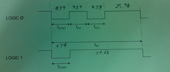
My first dig at PASM due to requirement. The logic diagram is also attached. May I request anyone to see if I've made any stupid mistakes? Thanks.
Jon, if you see this, may I check with you, how do you set a constant number of #24 to account for the setup/call/return in the pauseus routine? Is it a common known value or how should I calculate it?
Jon, if you see this, may I check with you, how do you set a constant number of #24 to account for the setup/call/return in the pauseus routine? Is it a common known value or how should I calculate it?
' -----------------
' Write Byte to device
' -----------------
owwrbyte                rdlong  value, iodata                   ' get byte from
                        mov     bitcount, #8                    ' 8 bit counter
wrloop                  shr     value, #1               wc
                        mov     usecs, #26
        if_c            add     usecs, #9
        if_c            jmp     #:wronebit                      ' Logic 1 = low
                        or      dira, owmask                    ' Logic 0 = low
                        call    #pause434us
                        andn    dira, owmask                   ' Logic 0 = high
                        call    #pause434us
:wronebit               or      dira, owmask                   ' Logic 0 & 1 = low
                        call    #pause434us
                        andn    dira, owmask                   ' High till end Time_bit
                        call    #pauseus
                        djnz    bitcount, #wrloop
                        wrlong  ZERO, cmdsel
                        jmp     #owmain


' ---------------------
' Pause in 4.34 microseconds
' ---------------------
pause434us              mov     ustimer, cnt                    ' sync with system clock
                        sub     ustimer, #24                    ' <-- account for setup/call/return, value is commonly known?
                        add     ustimer, four34ustix            ' set timer for 4.29 us (remove 0.05 us for waitcnt)
                        waitcnt ustimer, four34ustix            ' wait and reload
pause434us_ret          ret


' ---------------------
' Pause in 1 microseconds
' ---------------------
pauseus                 mov     ustimer, cnt                    ' sync with system clock
                        sub     ustimer, #20                    ' account for setup/call/return
                        add     ustimer, oneustix               ' set timer for 1 us
usloop                  waitcnt ustimer, oneustix               ' wait and reload
                        djnz    usecs, #usloop                  ' update delay count
pauseus_ret             ret
575 x 245 - 38K
Comments
' -----------------
' Write Byte to device
' -----------------
owwrbyte                rdlong  value, iodata                   ' get byte from
                        mov     bitcount, #8                    ' 8 bit counter
			mov     waittime, cnt                   ' this is used in all waitcnt
                        add     waittime, 4_34delay
wrloop                  shr     value, #1               wc
        if_nc           mov     usecs, shortdelay
        if_c            mov     usecs, longdelay
        if_c            jmp     #:wronebit                      ' Logic 1 = low
                        or      dira, owmask                    ' Logic 0 = low
                        waitcnt waittime,4_34delay
                        andn    dira, owmask                   ' Logic 0 = high
                        waitcnt waittime,4_34delay
:wronebit               or      dira, owmask                   ' Logic 0 & 1 = low
                        waitcnt waittime,4_34delay
                        andn    dira, owmask                   ' High till end Time_bit
                        waitcnt waittime,usecs
                        djnz    bitcount, #wrloop
                        wrlong  ZERO, cmdsel
                        jmp     #owmain


4_34delay               long    constant( ((CLKFREQ / 1_000 ) *  4_340) / 1_000 )
shortdelay              long    constant( ((CLKFREQ / 1_000 ) * 25_980) / 1_000 )
longdelay               long    constant( ((CLKFREQ / 1_000 ) * 34_660) / 1_000 )
The calculation of the delays is like that because we are in integer domain. So, only dividing by 1_000 (=> shift to ms) in the first step keeps as much digits as possible whilst avoiding an overflow.( CLKFREQ/1_000_000 * time is the general formula, but does not work good in integer domain. )
This is the quick and dirty implementation, because in the long periode you add some time to the waitcnt for the code which runs until setting the next start-bit. But this should be deviation which does not make problems because we talk about <1us.
If you want it completely perfect you can simply move the waitcnt usecs to another position and do it after all the code that gets the next bit.
rd[COLOR="orange"]byte[/COLOR]  value, iodata
                mov     bitcount, #8

                mov     cnt, cnt
                mov     cnt, #9

:loop           waitcnt cnt, [COLOR="blue"]short[/COLOR]
                or      dira, owmask            ' low
                waitcnt cnt, [COLOR="blue"]short[/COLOR]
                andn    dira, owmask            ' high
                shr     value, #1 wc            ' sample bit
                waitcnt cnt, [COLOR="blue"]short[/COLOR]
                muxnc   dira, owmask            ' low/high
                waitcnt cnt, [COLOR="blue"]tail[/COLOR]
                andn    dira, owmask            ' high
                djnz    bitcount, #:loop

                waitcnt cnt, #0                 ' guarantee last bit tail

                wrlong  ZERO, cmdsel
                jmp     #owmain

short           long    347                     '  4.3375us @80MHz
tail            long    2079                    ' 25.9875us
To answer your question, the logic is OK. But as mentioned earlier, having dedicated delay code is overkill here. I removed an earlier comment as for some unexplained reason I had [thread=137206]a 0.1us delay[/thread] stuck in my head (too much alcohol maybe).Thanks Mark. So that's why its #24.
Got it. Yes, I understand now. I'll implement delay calculation in this manner instead. Thank you MagIO2.
Hey Marko! Thank you but it took me quite a while to understand ... sorry I have some questions:
1. what does this means? I thought cnt is a register & cannot be used as a destination operand?
                mov     cnt, cnt
                mov     cnt, #9
2. I like this!
                shr     value, #1 wc            ' sample bit
                :
                muxnc   dira, owmask            ' low/high
3. I'm a little confused, when its logic 0:
               :
                waitcnt cnt, [COLOR=blue]short[/COLOR]
                muxnc   dira, owmask            ' low/high
                waitcnt cnt, [COLOR=blue]tail                          '<---- should the "waitcnt cnt, short" be here and ...? [/COLOR]
                andn    dira, owmask            ' high
                djnz    bitcount, #:loop [COLOR=#0000cd]              '<---- should the "waitcnt cnt, tail" be here before the djnz ?[/COLOR]
               :
4. I don't see how adding #0 to waitcnt means the tail is selected?
0.1 usecs ...
Note "shadow RAM' is the actual RAM location that exists at the cog memory address used for some register. There's a RAM location corresponding to each of the Prop's I/O registers, but they're only accessible under some circumstances because the I/O register takes precedence when processing the source field of an instruction. When processing the destination field of an instruction, the shadow RAM location is always written. The I/O register is read when it's read-write, but the I/O register is not used when it's read-only. Instruction fetches always use the shadow RAM.
So, does it explains the reason why Marko added #9 to factor in the cycle time for the previous MOV & this WAITCNT instructions so that the pulse duration is as accurate as possible?
So, is this shadow RAM something like cache? I won't get such jems from the manual ....
And don't confuse cog RAM with hub RAM (hub RAM is byte-addressed, cog RAM is long-addressed)
The manual does describe this as far as I remember (particularly in the descriptions of the various special registers).
In PASM waitcnt works slightly different (compared to SPIN that is). It waits for a match on its dst value, then adds src for the next match.
:loop waitcnt cnt[COLOR="orange"]{ref or ref+3*short+tail}[/COLOR], short or dira, owmask waitcnt cnt[COLOR="orange"]{ref+short}[/COLOR], short andn dira, owmask shr value, #1 wc waitcnt cnt[COLOR="orange"]{ref+2*short}[/COLOR], short muxnc dira, owmask waitcnt cnt[COLOR="orange"]{ref+3*short}[/COLOR], tail andn dira, owmask djnz bitcount, #:loop waitcnt cnt[COLOR="orange"]{ref+3*short+tail}[/COLOR], #0HTHAfter going thru your code for long while (including talking to myself), I finally understood =D !!! Thank you very much Marko! Yes, its a very different mind-set for me. Have a good weekend All.
Thank you Mark.