Propeller Quickstart Board is excellent
Parallel Processing Enthusiasts,
I have to say that the new Parallax Propeller Quickstart board is an excellent piece of engineering. It has just the right amount of features needed to avoid both breadboards and custom soldering because of the 8 included LEDs and the 40 pin header - It is at the sweet spot for usability, competitive advantage and volume pricing. Parallax has really outdone themselves by providing the option of powering the board via USB. I can get 7 quickstart boards running full speed at around 0.15A per board without adding a powered hub. With a powered hub 16 boards run fine via Propellent.
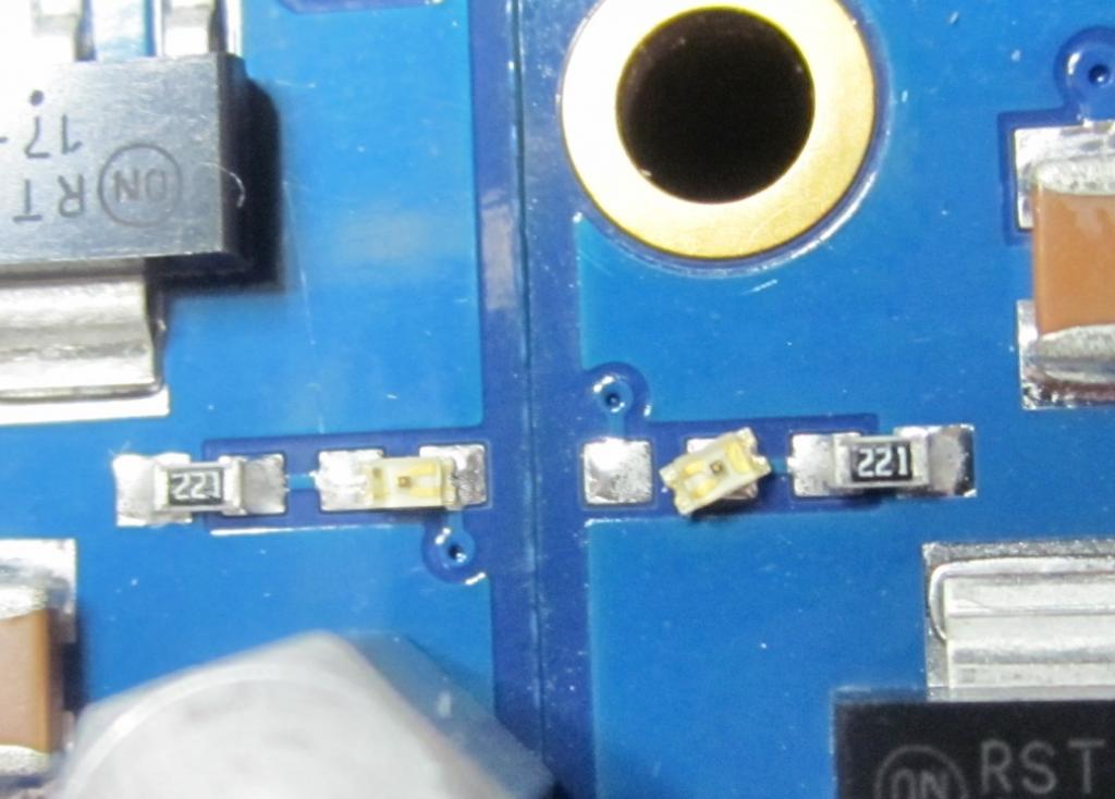
My question is about modifying the board via a single solder fix. I would like to move the power LED's as indicated in the included photo on the right. I do not have experience with surface mount - I have soldered through-hole. Before I touch the board, can I use a regular soldering iron on the two pads for a couple seconds to move the LED or should I use a toaster oven (hopefully not). I am assuming that there is nothing different between surface mount soldering except for doing it under a microscope.
The picture is of two quickstart boards side by side - the one on the right will be modified, the one on the left is a reference.
thank you in advance
/michael


Comments
To resolder it do this:
2. Using solder wick, remove the solder from one of them.
3. With tweezers hold the LED against both pads, and melt the solder on the pad that still has solder.
4. Press the LED flat onto both pads, and let the solder cool.
5. Solder the LED to the remaining pad.
6. Go back to the first pad, if necessary, and touch it up with a little fresh solder.
-Phil
Be careful with LEDs as they (were some years ago) more fragile than normal ICs heatwise. So apply the heat for as short a time as possible.
The ideal is to heat BOTH pads at the same time, and avoid 'dancing the tip' - that means either the two-barreled Tweezer style Soldering irons, such as
http://shop.vetcosurplus.com/catalog/images/XY-TWZ60-1.jpg
or making a simple heat-header from anything heavy enough : heavy copper wire or copper sheet.
Hot-air blower.irons are also ideal for this, but they are not cheap.
-Phil
Hard to be sure..
When he said ["move the power LED's"] (plural) I figured he intended to change many boards, because of some alignment issue (My guess was swap the R and Series LEDs ?, or even move the LED to a CUT-trace somewhere else... )
Besides, Parallax would not really ship a board with a skewed power LED, would they ?
Very good details, appreciated, i will post an after photo shortly. This post is indirectly directed at the QC or VE dept - that i have the highest respect for. My 1st batch of 18 boards are all unmodified and function beautifully. Power indication is undefined in one case but does not affect functionality. Aside: What should we do with all of these very nice artworked cardboard boxes
/michael