

How do we find the correct resistance for a component
 MunifTheGreat
Posts: 20
MunifTheGreat
Posts: 20
This is a project of my own I want to do.
It's a laser security system.
I have programmed the circuit as the same as a pushbutton.
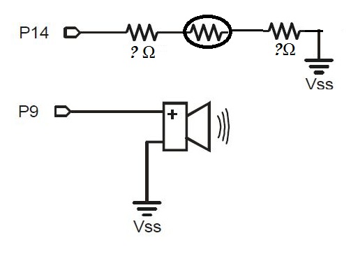
Here is a schematic representing the circuit.

My question is how can I figure out what resistors to put between the photoresistor
How can I determine the resistance if I'm testing this circuit in the dark with a laser ( unknown specifications)
Will it work?
Thank You.
__________________________________
Sorry, I speak better french than english and I'm new in electronics.
It's a laser security system.
I have programmed the circuit as the same as a pushbutton.
Here is a schematic representing the circuit.
My question is how can I figure out what resistors to put between the photoresistor
How can I determine the resistance if I'm testing this circuit in the dark with a laser ( unknown specifications)
Will it work?
Thank You.
__________________________________
Sorry, I speak better french than english and I'm new in electronics.
503 x 397 - 28K
Comments
Photoresistor data?
This is just one example out of hundreds you can find with a Google search.
In this example the wire marked V is where you would connect to your Stamp pin P14. The only modification I would make would be to add a 220 Ohm resistor from P14 to the connection V, this would be a precautionary measure to prevent excess current damaging your Stamp chip
Jeff T.
Resources
Measure Resistance and Capacitance -·Updated (2/2/10) - found on the following link.
http://forums.parallax.com/showthread.php?89958-Propeller-Education-Kit-Labs-Tools-and-Applications
http://forums.parallax.com/showthread.php?111176-PE-Kit-Tools-Measure-Resistance-and-Capacitance&p=791692#post791692
Plus we need to know what model (part number) photoresistor you are using.
The photoresistor circuit you have drawn might not work depending on what you have in mind:
P14 as an input would do nothing as the photoresistor doesn't generate a voltage
I suppose you could set P14 as an output, then current limit it to 5ma or so with the photoresistor at the lowest resistance (bright light?) Use ohm's law for this.... then you would monitor the voltage drop with another pin, or you might be able to read the state of P14.
The second one you don't need at all.