Problems with the Parallax 3-axis Compass Module HMC5883L Demo Program?
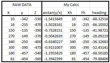
I am attempting to use the Parallax 3-axis Compass Module HMC5883L. I downloaded, updated and ran the demo program from the Parallax site, HMC5883L_demo.spin (attached). The resulting output would only "swing" through about 90 degrees and remained in the NE quadrant. I dumped the RAW data from the program as I rotated the sensor 360 degrees, stopping at 8 points (N, NW, W, NW, S, SE, E, NE) to capture the raw data. In looking at the demo code, the aziadjust routine is using the value of raw X to and arctan(Y/X) to determine the quadrant (NW, SW, SE, NE) of the the heading. Looking at the raw data (X & Y) and calculated arctan values (see attached .jgp), X is always > 0 and arctan(y/x) is always < 0 - so no wonder the quadrant always fixed in the NE quadrant. Suspecting that the raw data isnt being read off of the sensor registers correctly, I have been staring at these methods can't find any obvious defects.
I am puzzled. I have yet to find any issues with any of the demo programs provided by Parallax - yet the install and localization for this sensor is very basic, so I am assuming something must be amiss in the demo program.
Any help is greatly appreciated.
Thanks!
Greg
I am puzzled. I have yet to find any issues with any of the demo programs provided by Parallax - yet the install and localization for this sensor is very basic, so I am assuming something must be amiss in the demo program.
Any help is greatly appreciated.
Thanks!
Greg


Comments
I just picked up a Compass Module today a ran it on a PPDB with no problems.
Question on your "_clkfreq = 100_000_000" . How did you arrive at that setting?
Did you change SL32_INTEngine_2.spin any?
Jim
Jim
What error did you find in the documentation? I looks consistent to me.
Are you getting good results with your module?
Thanks,
Greg
Hi Greg,
I'm re-arranging my lab right now, so I have everything torn apart right now.
Monday or Tuesday, I'll set up another board with a 6.25 Mhz xtal and try out the different codes.
My test yesterday was very quick just to make sure the module was working. I'd like to try and get the raw data and look at it also.
Jim
The normal way to get quadrant information is to call atan2(y, x) - atan2 is the version that looks at the signs of the y and x values to determine the quadrant (which is information that is lost doing the divide)
If the "SL32_INTEngine_2" object (which I can't find on the obex BTW) doesn't support atan2 or arctan2 or something equivalent you'll need to adapt the code to look at the signs of x and y.
http://en.wikipedia.org/wiki/Atan2
We want 'azimuth bearing'
We want horizontal coordinates
Everyone chant this over and over (and email tech support to look into the conversion)
in the meantime a temporary fix. gives 360 but theres a 6 degree +/- thing going on at the quadrant corners
1. in VAR section add WORD azvalue
2. in PUB MAIN add term.str(String(" ") into the repeat
3. in PUB MAIN add term.dec(azvalue) into the repeat
4. in PUB Azijust : value at bottom of it add azvalue := value
look at the terminal at 9600 baud and there it is
My_Compass.spin
SL32_INTEngine_2.spin
http://tymkrs.tumblr.com/post/22237323716/parallax-compass-module-3-axis-hmc5883l-29133
http://tymkrs.tumblr.com/post/22258810035/parallax-compass-module-3-axis-hmc5883l-29133-part
Let me know if this helps any?
Is there a mention of calibrating the compass by finding its offsets?
Because any compass I've used that wasn't calibrated for offset would tend to behave similarly to how you are describing. ("Placing the compass on a flat surface (the pool table came in handy for this purpose) I got somewhat better results - but still, moving the module through, say 90 degrees, doesnt result in a 90 degree change in the reading - in some quadrants I get less, in others I get more.")
Have a look over here: http://www.bot-thoughts.com/2011/04/quick-and-dirty-compass-calibration-in.html
The HMC5883L will run on supplies from 2.16V to 3.6V. Unless the board you're using has a voltage regulator to reduce the 5V to a safe level, it will likely damage the sensor board.
Edit: The Parallax board does have a regulator so 5V is fine when using the Parallax board.
I've successfully used several different HMC5883L sensors many times powered with 3.3V. Here's a link to my HMC5883L code. I attempted to use a HMC5883L sensor for attitude feedback in this project but I had the sensor too close to the servos. Once I moved the sensor away from the servos a few inches, it worked much better.
I plan to post a similar reply to the other thread about this sensor. Again, unless the board with the HMC5883L sensor has a way of regulating the power supply, it should NOT be powered with 5V (the Parallax board does regulate the power so 5V is fine when using it). 3.6V is the maximum voltage to be used with the sensor.
Edit: The Parallax board should work with a power source between 2.7V and 6.5V. It seems strange the Parallax module didn't work correctly when powered by 3.3V. I'm pretty sure I have the Parallax version of this sensor. I'll try to find it to see if I can replicate Iratenate's problem.