Very Basic... Stamp Help
Ok, quick story.
I'm a bit nervous posting here asking for help. I need to preface this with the usual "I'maNewb don't be too harsh... yadda yadda" after reading some of the posts here. I messed around with pbasic a few years back to make some leds blinky blinky and flip reed relays for lasers and other low-voltage stuff. I have a few Basic Stamps laying around and a project where I can apply them.
With that being said. I have used the search button, and have not come up with an answer that I am looking for. I am a bit of an e-tard so that could be part of the problem or maybe my problem is to basic for this forum. I have found a few schematics that say they are the best way to go, but nothing from any reliable sources.
Here is what I am looking for:
I need help finding the best, safest, cheapest circuit to utilize logic signal in everyday applications. If you cannot see what I am asking for, I would like the schematic for something like this: http://www.ramseyelectronics.com/cgi-bin/commerce.exe?preadd=action&key=RI1
My application:
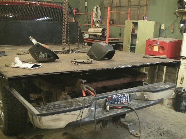
I run a small fab shop where we, among other things, take things like this:

And do things like this:

As we progress in our operation and fabrication techniques I do not want to leave the electronics of our products in the dust. As you can see we implicated some nice looking led tail/brake/turn signal lights to the back of this project. My goal is to make these light sequentially, from inner most to outer, when receiving a turn signal, and then hold that until the signal is released. This way I can time them to be in sync with the signal sent with the trucks flasher unit and not mess around with bypassing it, and then light sequentially and hold when a brake signal is received.
If the stamp is not the best route to go here, speak up and let me know. However, I still need the best solution for logic to real world power for when I do things like this: http://www.instructables.com/id/CNC-Plate-MarkerEngraver-Homemade/ On this project I am stuck using the relay put in place by the manufacture of the controller because I do not want to risk damaging the i/o pins that are available. I will use the i/o's that are there once I have a solution.
Would something like this be better than the other product link that I posted? If so, why and a schematic please! http://www.ramseyelectronics.com/cgi-bin/commerce.exe?preadd=action&key=OM2
I'm a bit nervous posting here asking for help. I need to preface this with the usual "I'maNewb don't be too harsh... yadda yadda" after reading some of the posts here. I messed around with pbasic a few years back to make some leds blinky blinky and flip reed relays for lasers and other low-voltage stuff. I have a few Basic Stamps laying around and a project where I can apply them.
With that being said. I have used the search button, and have not come up with an answer that I am looking for. I am a bit of an e-tard so that could be part of the problem or maybe my problem is to basic for this forum. I have found a few schematics that say they are the best way to go, but nothing from any reliable sources.
Here is what I am looking for:
I need help finding the best, safest, cheapest circuit to utilize logic signal in everyday applications. If you cannot see what I am asking for, I would like the schematic for something like this: http://www.ramseyelectronics.com/cgi-bin/commerce.exe?preadd=action&key=RI1
My application:
I run a small fab shop where we, among other things, take things like this:

And do things like this:

As we progress in our operation and fabrication techniques I do not want to leave the electronics of our products in the dust. As you can see we implicated some nice looking led tail/brake/turn signal lights to the back of this project. My goal is to make these light sequentially, from inner most to outer, when receiving a turn signal, and then hold that until the signal is released. This way I can time them to be in sync with the signal sent with the trucks flasher unit and not mess around with bypassing it, and then light sequentially and hold when a brake signal is received.
If the stamp is not the best route to go here, speak up and let me know. However, I still need the best solution for logic to real world power for when I do things like this: http://www.instructables.com/id/CNC-Plate-MarkerEngraver-Homemade/ On this project I am stuck using the relay put in place by the manufacture of the controller because I do not want to risk damaging the i/o pins that are available. I will use the i/o's that are there once I have a solution.
Would something like this be better than the other product link that I posted? If so, why and a schematic please! http://www.ramseyelectronics.com/cgi-bin/commerce.exe?preadd=action&key=OM2

