I2C help
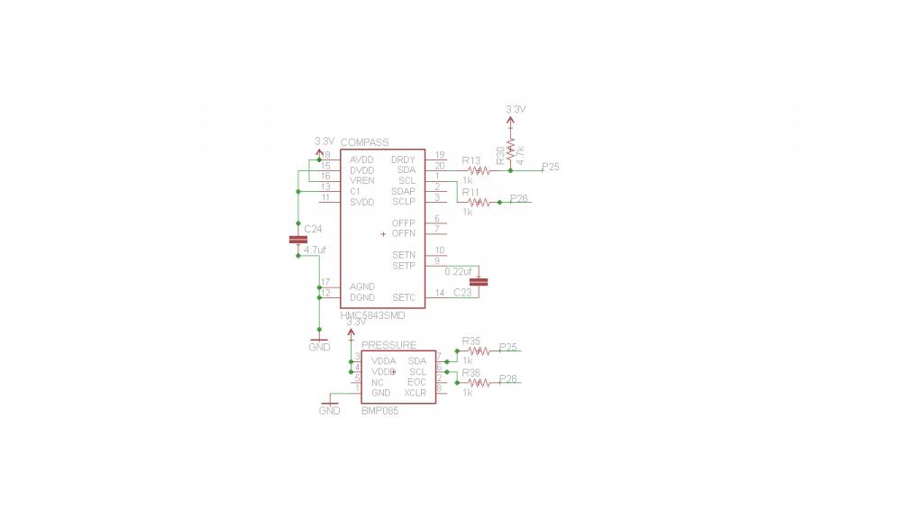
So yesterday I put a post up in asking for help on the hardware portion of my project and i'm glad to have that all fixed up  , so now its on to the software side >.<. Currently I have a HMC5843 and a BMP085 connected to my propeller. The I2C lines are connected together and each line goes through a 1k resistor and the SDA line has a 4.7k resistor pullup (the schematic tells this story better than me).
Running a I2C scan on pins 25 and 26 I can detect two addresses:
%0011_1100 0001_1110
%1110_1110 0111_0111
The first one corresponds to the HMC5843 address and the second one to the BMP085. This means that I am detecting the two chips on the line meaning that they are communicating. Right?
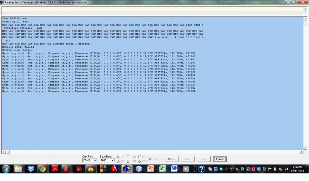
The problem comes when actually trying to communicate to the device. The screen shot of the PST shows what I'm dealing with. I'm using a modified version of Tim Moore's quadtest program which uses a version of the Basic I2C Driver. Heres a snipet of the code:
Is the issue that I don't have a pullup on the SCL line? Is 4.7k enough or should I change both values to 10K? If it is detecting those two addresses am I implementing them correctly?
Running a I2C scan on pins 25 and 26 I can detect two addresses:
%0011_1100 0001_1110
%1110_1110 0111_0111
The first one corresponds to the HMC5843 address and the second one to the BMP085. This means that I am detecting the two chips on the line meaning that they are communicating. Right?
The problem comes when actually trying to communicate to the device. The screen shot of the PST shows what I'm dealing with. I'm using a modified version of Tim Moore's quadtest program which uses a version of the Basic I2C Driver. Heres a snipet of the code:
  i2cScan.i2cScan(26)                               'display I2C devices

  comAddr := %0011_1100          'compass I2C address
  pressureAddr :=1110_1110

  uarts.str(0, string("HMC5843 init: "))
  if compass.Init(26, comAddr, true)                'init compass
    uarts.str(0, string("ok", 13))
  else
    uarts.str(0, string("failed", 13))

  uarts.str(0, string("BMP085 init: "))
  if pressure.Init(26, pressureAddr)                'init presssure sensor
    uarts.str(0, string("ok", 13))
  else
    uarts.str(0, string("failed", 13))
Is the issue that I don't have a pullup on the SCL line? Is 4.7k enough or should I change both values to 10K? If it is detecting those two addresses am I implementing them correctly?


Comments
It is more likely that your software is not correct. What driver object are you using? There are a few in the obex.
It is more likely that the initialisation sequence is not correct. I would however, put a pullup on SCL just in case.
Looking at your wschematic, perhaps the 1K series resistors are causing a problem because you are effectively using the 4K7 & 1K as a voltage divider. I suggest either changing the pullups to 10K or link out the 1K. You do not need the 1K because all devices are running on 3V3.
SDA and SCL are driven. Remove those 1Ks as Cluso99 suggests. Adding resistance to the I2C bus is not good, nor is adding capacitance.
Also, post the top level object that uses Basic_I2C_Driver.spin.
SDA should always have a pullup. SDA is a bi-directional bus and therefore, the driver cannot keep the SDA line driven. Some I2C devices may only drive the line low, meaning a pullup is mandatory.
measure the pull up current to set there communication speed to 100KHz, 400KHz or 1.2MHz.
I am using the same quadtest1 code to test my BMP085. I have 4.7k pullups on both SCL & SDA lines, and the 100nF cap recommended in the BMP085 datasheet. I uncommented the following code" i2cSCL := config.GetPin(CONFIG#I2C_SCL1)" to use pin 28 on a Quickstart board. I am getting similiar results to Thric's compass module.
I also tried the code without the pullups and it returned the same results. I also found a program called BAROMETRO.spin which uses the same Basic_I2C_Driver and bmp085Object.spin files. The temp and pressure values returned zeros using this code.
Cluso99 suggested "It is more likely that the initialisation sequence is not correct." I think his idea holds the answer, I do not know how to resolve the problem yet, maybe it lies in the config file as when I run the code quadtest1, it finds an I2C device, but the BMP085 init fails.
This is my first attempt with I2C and any help would be appreciated.
Rob
I found my problem to be in the hardware side of my setup, would you mind telling how you set this up (custom pcb, breakout board, etc)?
Just a shot in the dark, but did you comment out the line following the line you un-commented?
I did uncomment the line "i2cSCL := config.GetPin(CONFIG#I2C_SCL1) "
and commented the line below it. I check my hardware agaiin which appears correct. I am using the QuickStart board with SCL going to P28 and SDA to P29.
Are there any other code changes that need to be done that I may have overlooked?
Thank You,
Rob
1. I am using spin to do the I2C driver
2. There does not seem to be any timing whatsoever
3. The start bit is not really performed (its by accident)
4. There does not seem to be any looking for the ack bit
I just wanted something simple. Anyway, I am doing my own thing here and will post the results. I have done I2C before with the gyro and accelerometer on my quadcopter, but I wanted a simple piece of spin code for my RTC.
I have my DS1340C working too
Now to code the DS1340C as a standalone object.
Maybe it could be used for time, speed distance problems on your quad as in if the quad is running in an autonomous mode and was to lose a gps signal it could use a magnetic heading, altitude info, airspeed to return to base or back into an rf range to regain manual flight control? Just a thought!
I look forward to seeing you publish a stand alone object