Hardware debugging help?
Hi, I'm having some issues (again  )with my current propeller project and the main focus is on programming my chip.
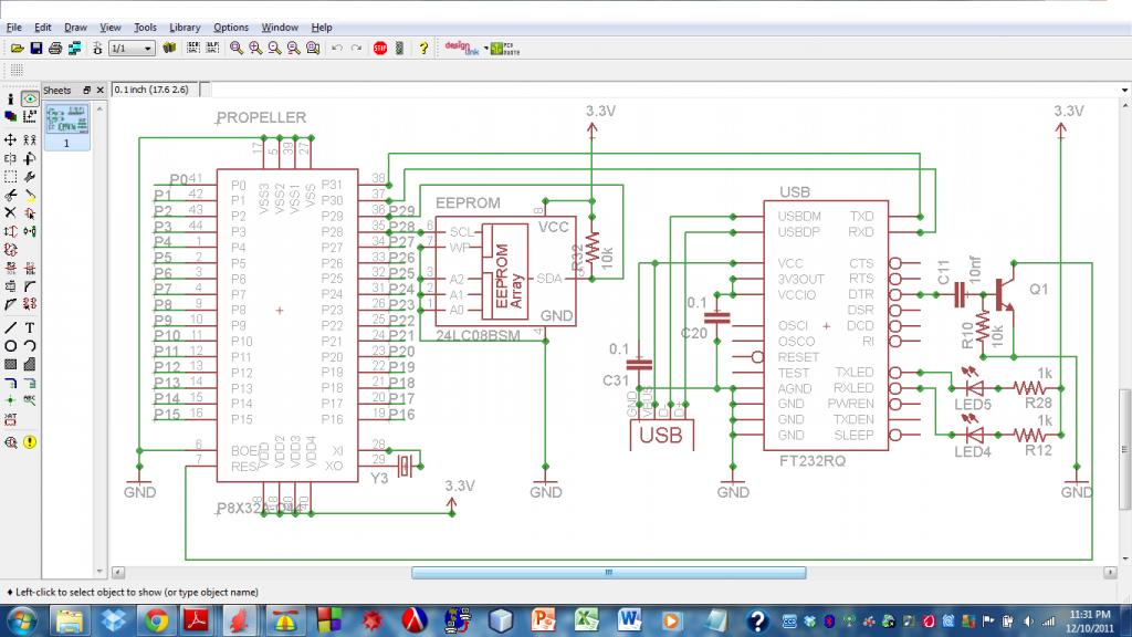
Right now i'm using a custom PCB that uses a FT232RQ chip and the reset transistor circuit to program my propeller (part of the schematic is attached, there are plenty of bypass capacitors that are just not shown). The issue comes up when I try to program; sometimes it works and sometimes it doesn't. i know that that my PC knows that the FTDI chip is there as it scans the comport, but for some reason it doesn't detect the propeller that's connected to it. The times that I have been able to program it I've been able to run the PST object and communicate to my terminal screen through my on-board USB and through my XBEE.
I have noticed a pattern, however, that i believe has something to do with it:
leaving the board to sit for a while (more than an hour or so) I can program it and I can program it repeatedly meaning that if i don't do anything to the board it'll be fine.
Once i add my xbee to my PCB the programing stops, it scans the port but doesn't detect the propeller. The propeller does reset though.
What could be causing the randomness in programming ability?
Are the values for the resistor and capacitor in the Reset circuit correct (as a side note the cap isn't 10nf its actually 22pf)? or more specifically why does the ASC (http://mghdesigns.com/index.php?main_page=product_info&products_id=4) have different resistor and capacitor values than the gadget gangster board (http://gadgetgangster.com/find-a-project/56?projectnum=257)?
I think it may have something to do with the reset curcuit, but then again it does reset fine, even when programming failed (as in my PC scans and fails to connect but reset occurs).


Comments
My guess -- Yours Voltage regulators leave to little current.
Are you running off a battery of some kind?
Edit: What does the message 'EEPROM programming error on COM14' actually mean?