S2 Expansion Board
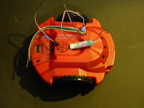
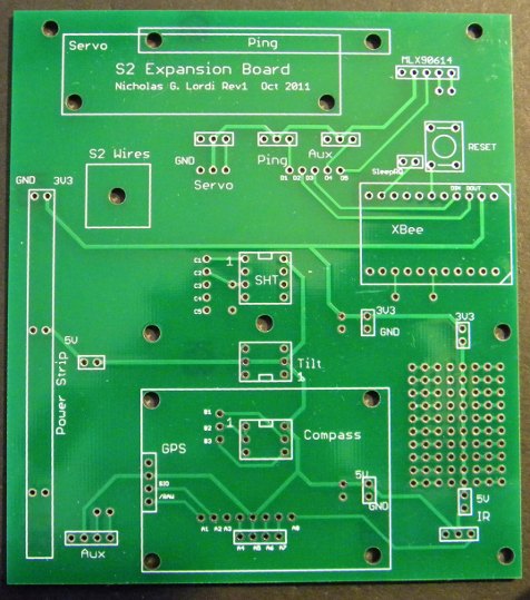
My objective was to make the S2 hacker port available in the form of an expansion board placed on top of the S2. My first step was to provide external access to the port by drilling a hole in the top of the S2 shell, through which cables connected to 8 port pins (6 digital i/o & 2 analog inputs) and the 5 volt power supply would pass. Attached Fig_S2A shows the placement of the hole on the S2 cover and the cabling connected to the hacker port inside the S2 body. Also shown in the image is a standoff constructed from a plastic tube which fits in the pen port and is attached to the expansion board. There are two small holes drilled in the front of the S2 on each side. These align with the holes in the top extreme right and left of the expansion board shown in Fig_S2B.
While there are many possible designs for expansion boards, I chose a design which includes space for those sensors I decided to add to the board while allowing for sufficient flexibility to add other modules. The devices I planned to install are labeled on the board. These include a compass or GPS, a tilt sensor, the SHT11, a servo and/or ping. Since the hacker port pins are passed through a level shifter with the outputs pulled high to 5V, I elected to power the devices at 5V, except for the XBee. The power strip on the left side provides the 3.3V required by the XBee, as well as allowing the board to be powered externally. Note the small prototyping area on the right side. Additional holes were added to facilitate attachment of daughter boards, e.g., a QuickStart.
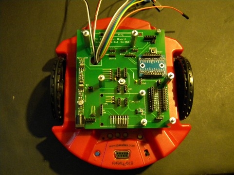
Fig_S2C shows the board with all sockets, headers, and some standoffs in place. The hole if the board labeled 'S2 Wires" was enlarged to allow room for the wire connectors. Machine screws were placed in the two top holes that aligned with the small holes in the S2 to hold the board in place. Wires were color coded to identify the specific S2 propeller pins. The prototyping area was setup to allow addition of an Adafruit level shifter board. 5V power was provided to the board by connection of the 3 wire connector (includes analog input 0) at the bottom as well at the top (servo connection).
I will show some possible board configurations in the following post.
NickL


Comments
Fig_S2D shows a simple configuration where a solderless breadboard is attached. The XBee and prototyping areas are available for use.
Fig_S2E shows a configuration which includes the XBee, a Ping, SHT, 4 directional tilt sensor, and compass. The orange wire connects to the Ping, the grey wire to the Xbee din, the violet wire to the XBee dout through a 4.7K resistor, and the remaining 3 i/o wires to the compass.
Fig_S2F shows a configuration were the compass is replaced with a GPS module, the Ping is attached to the servo, and a heat sensor is connected to the port on the right of the servo.
Fig_S2G shows the addition of a QuickStart module, adding more pins to avoid the S2 limit where only 6 i/o pins are available.
I have also attached a version of the S2 default demo which allows the user to select the demo from a PC terminal emulation by wireless XBee, rather than pressing buttons on the S2.
NickL
Your dual-prop S2 has some serious firepower now!
-Phil