

TSL1401-based Absolute Encoder
 Phil Pilgrim (PhiPi)
Posts: 23,514
Phil Pilgrim (PhiPi)
Posts: 23,514
Several years ago, I designed a demo absolute encoder for TAOS using their TSL1401 linear array sensor -- the same sensor used in the TSL1401-DB sold by Parallax. The original design was derived from work done by David Mehrl of Texas Tech University titled, "Position Detection Using Maximal Length Sequences", available here:
That paper describes how to use a maximal-length sequence (MLS) to build a position sensor (e.g. absolute encoder). The encoding for the various bars in the encoder pattern was NRZ (non-return-to-zero), IOW, straight binary. Because NRZ is not self-clocking, I chose to use a PWM encoding (which is self-clocking), where 1's were encoded as wide bars; 0's as narrow bars. It is described in this paper:
This past week I've converted that work to run with the TSL1401-DB, plugged into a Propeller Backpack. Rather than using PWM this time, though, I switched to Manchester encoding. In this scheme, a 1 bit is represented as a 0-to-1 transition in the middle of the bit cell; a 0 bit, as a 1-to-0 transition, as shown in the following illustration:

Manchester encoding has the advantage of half the number of transitions compared to PWM, while still being self-clocking. This results in a less-dense barcode representation, thus relaxing the requirements for imaging resolution. The downside of Manchester encoding is that it's a little harder to decode on the fly, since you don't know right away whether a given edge is in the center of a bit cell or between two bit cells. The result is that an endless stream of 0-bits looks identical to a stream of 1-bits, if you don't know the starting point: ...1010101010101010101...
One way to decode a Manchester bitstream is to wait for a 00-to-1 or a 11-to-0 transition. Such a transition has to occur in the middle of a bit cell. From there you're in sync, and decoding is a breeze. In this application, since we're statically looking at only a small portion of a long bitstream, we can't afford waiting to begin decoding after a "long bar" or "long gap", since we could easily pass by most of the code that we must use to determine our position. For this reason, I decided to maintain two decoding streams simultaneously and to decide at the end which one is correct. Here's an illustration of that approach:

Each edge is assumed to occur in the center of a bit cell in one decoding stream or the other. Which one depends on a one-bit counter that's toggled at the end of every short bar or gap encountered (but not at the end of long bars or gaps) while scanning through an image. When this counter is zero, a bit is added to the "even" decoding stream; when one, to the "odd" stream. At the end, one decoded word will have more bits in it than the other, and that will be the correct decoding.
To keep things simple, I produced a linear encoded strip that uses a seven-bit MLS:

By decoding any seven or more Manchester bit cells in the strip, we can tell where on the strip we're looking, since each seven-bit code is unique. (Actually, since 0000000 and 1111111 are both valid codes, it's necessary to see eight or more bit cells, to guarantee that a least one wide bar or gap is included.) Because the MLS codes are not sequential, it is necessary to look up the actual position in a table, indexed by the seven-bit MLS value.
But we can take this one step further. Each bit cell will have a certain displacement from the center of the TSL1401's field of view. By measuring the displacement of the center bit cell, relative to its overall width, we can add another three bits of precision to the position determination, resulting in ten bits of resolution, or more than 1000 resolvable positions along the strip.
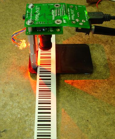
Here's a photo of my test setup, which worked as I had hoped:

Attached is a Spin archive with the full source code, along with a PDF that includes the strip that I used and a circular version of the same encoding.
If you try to replicate this proof-of-concept project, be sure to use the brightest illumination source available. That will force the autoexposure algorithm to use short exposure times. This is important when the code strip or code wheel is in motion, because image blur will result in erroneous decoding.
This has been a pretty brief presentation, and I've glossed over some details. So, as always, questions and comments are welcome!
-Phil
That paper describes how to use a maximal-length sequence (MLS) to build a position sensor (e.g. absolute encoder). The encoding for the various bars in the encoder pattern was NRZ (non-return-to-zero), IOW, straight binary. Because NRZ is not self-clocking, I chose to use a PWM encoding (which is self-clocking), where 1's were encoded as wide bars; 0's as narrow bars. It is described in this paper:
This past week I've converted that work to run with the TSL1401-DB, plugged into a Propeller Backpack. Rather than using PWM this time, though, I switched to Manchester encoding. In this scheme, a 1 bit is represented as a 0-to-1 transition in the middle of the bit cell; a 0 bit, as a 1-to-0 transition, as shown in the following illustration:
Manchester encoding has the advantage of half the number of transitions compared to PWM, while still being self-clocking. This results in a less-dense barcode representation, thus relaxing the requirements for imaging resolution. The downside of Manchester encoding is that it's a little harder to decode on the fly, since you don't know right away whether a given edge is in the center of a bit cell or between two bit cells. The result is that an endless stream of 0-bits looks identical to a stream of 1-bits, if you don't know the starting point: ...1010101010101010101...
One way to decode a Manchester bitstream is to wait for a 00-to-1 or a 11-to-0 transition. Such a transition has to occur in the middle of a bit cell. From there you're in sync, and decoding is a breeze. In this application, since we're statically looking at only a small portion of a long bitstream, we can't afford waiting to begin decoding after a "long bar" or "long gap", since we could easily pass by most of the code that we must use to determine our position. For this reason, I decided to maintain two decoding streams simultaneously and to decide at the end which one is correct. Here's an illustration of that approach:
Each edge is assumed to occur in the center of a bit cell in one decoding stream or the other. Which one depends on a one-bit counter that's toggled at the end of every short bar or gap encountered (but not at the end of long bars or gaps) while scanning through an image. When this counter is zero, a bit is added to the "even" decoding stream; when one, to the "odd" stream. At the end, one decoded word will have more bits in it than the other, and that will be the correct decoding.
To keep things simple, I produced a linear encoded strip that uses a seven-bit MLS:
By decoding any seven or more Manchester bit cells in the strip, we can tell where on the strip we're looking, since each seven-bit code is unique. (Actually, since 0000000 and 1111111 are both valid codes, it's necessary to see eight or more bit cells, to guarantee that a least one wide bar or gap is included.) Because the MLS codes are not sequential, it is necessary to look up the actual position in a table, indexed by the seven-bit MLS value.
But we can take this one step further. Each bit cell will have a certain displacement from the center of the TSL1401's field of view. By measuring the displacement of the center bit cell, relative to its overall width, we can add another three bits of precision to the position determination, resulting in ten bits of resolution, or more than 1000 resolvable positions along the strip.
Here's a photo of my test setup, which worked as I had hoped:
Attached is a Spin archive with the full source code, along with a PDF that includes the strip that I used and a circular version of the same encoding.
If you try to replicate this proof-of-concept project, be sure to use the brightest illumination source available. That will force the autoexposure algorithm to use short exposure times. This is important when the code strip or code wheel is in motion, because image blur will result in erroneous decoding.
This has been a pretty brief presentation, and I've glossed over some details. So, as always, questions and comments are welcome!
-Phil
576 x 174 - 13K
678 x 228 - 21K

640 x 30 - 9K

380 x 458 - 51K
Comments
So far I've used my line scan camera as sort of a scribbler vision system on steroids. I've tried to infer the presence of an object by looking for changes in brightness. I had a bar code reading project, but image scale was causing me grief. I like your solution of fixing the camera's distance to the subject because it simplifies things.
On a lighter note: Get it? Scan your post. That made me laugh out loud. It was intentional. Wasn't it?