

Guitar turner circuit
 mattm_nscc
Posts: 13
mattm_nscc
Posts: 13
Hello, i am doing a school project and part of it is to build a guitar turner circuit. I have found a thread on this fourm a while back about it and ive attahed the circuit and code below. My questions are, do you think it would be hard to modify the code so it out puts the the LCD and if i went the LCD route would i still need the shift registors ?
thanks Matt M
' TechnoRobbbo's Electric Guitar Tuner V2.0
' {$STAMP BS2}
' {$PBASIC 2.5}
'
'Declarations
tuneTmp VAR Word 'Tuning scratch pad
LoLim VAR Word 'Note Low Limit
HiLim VAR Word 'Note High Limit
tunePos VAR Word 'Note Accuracy 5 = in tune
result VAR Byte 'Look up variable
Note VAR Byte 'LED Note Image
WaveLen VAR Word 'Wave Length BS2 Timing
Zero VAR Word
'Constants and equates
GPin CON 0 'Sound input
DPin CON 3 'Display Data Pin
LPin CON 2 'Display Latch Pin
CPin CON 1 'Clock Pin
'initialize
OUTPUT 4
OUTPUT 5
LOW LPin
SHIFTOUT DPin,CPin,MSBFIRST,[0\16]
PULSOUT LPin,3
'
Main:
DO
'sum 5 full cycles of wavelength
WaveLen=0
PULSIN GPin,1,Wavelen
'18181
IF WaveLen<18182 AND WaveLen>275 THEN
DO WHILE WaveLen>4595
WaveLen=WaveLen>>1
LOOP
ELSE
Wavelen=0
Zero=0
ENDIF
'get index and target - BS2 Timing
IF WaveLen>0 THEN
result=0
LOOKDOWN WaveLen,>=[4416,4168,3934,3713,3505,3308,3122,2947,2781,2625,2478,2339,2208,2084,1967,1856,1752,1654,1561,1473,1390,1312,1239,1169,1104,1042,983,928,876,827,780,736,695,656,619,584,552,521,491,464,438,413,390,368,347,328,309,292,276],result
IF Zero.HIGHBYTE=Zero.LOWBYTE AND Zero.HIGHBYTE=result THEN
Zero=Zero<<8 + result
'Get LED Image
LOOKUP (result//12),[245,253,55,99,107,151,159,115,113,121,246,254],Note
'get limits and calculate tuning position
LOOKUP result,[4677,4415,4167,3933,3712,3504,3307,3121,2946,2780,2624,2477,2338,2207,2083,1966,1855,1751,1653,1560,1472,1389,1311,1238,1168,1103,1041,982,927,875,826,779,735,694,655,618,583,551,520,490,463,437,412,389,367,346,327,308,291],HiLim
LOOKUP result,[4416,4168,3934,3713,3505,3308,3122,2947,2781,2625,2478,2339,2208,2084,1967,1856,1752,1654,1561,1473,1390,1312,1239,1169,1104,1042,983,928,876,827,780,736,695,656,619,584,552,521,491,464,438,413,390,368,347,328,309,292,276],LoLim
'slow down display
tuneTmp = HiLim-LoLim
tuneTmp = (HiLim-WaveLen) * 10 /tuneTmp MAX 9
tunepos=DCD tuneTmp
'Ouput to Display
OUT4=tunepos.LOWBIT(0) 'output extra LEDs
OUT5=tunepos.LOWBIT(1)
tunepos=tunepos >> 2
SHIFTOUT DPin,CPin,MSBFIRST,[Note\8,tunepos.LOWBYTE\8] 'output to daisy chain
PULSOUT LPin,3 'latch display
else
Zero=Zero<<8 + result
ENDIF
ENDIF
LOOP
END
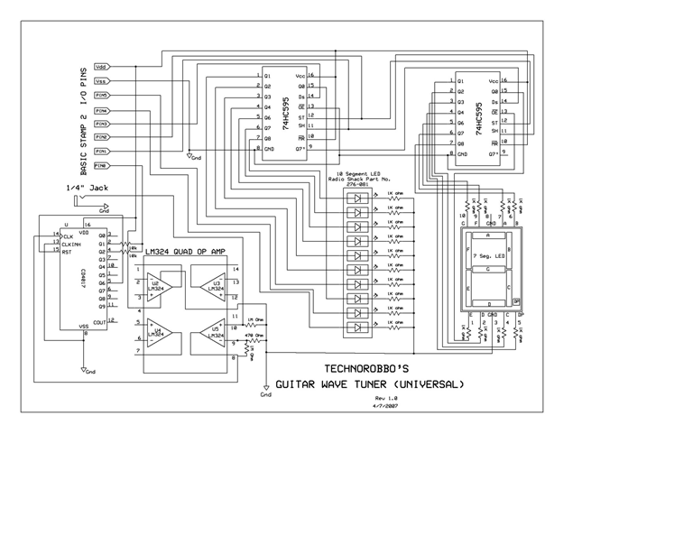
768 x 614 - 78K
Comments
thanks Matt M
My teacher said i may have to creat an look up table or something so each letter will be assigned a #
this is what we have now
"serout 15,84 [22,12, " Note = ", result ], it gives use the best looking results so far...
Thanks Matt M
Thanks Matt M