Shop OBEX P1 Docs P2 Docs Learn Events
Electrical Wiring Question: Transformer Connections — Parallax Forums

Electrical Wiring Question: Transformer Connections

eiplannereiplanner Posts: 112
edited 2011-11-14 12:37 in General Discussion
Pool Light XFMR.jpg


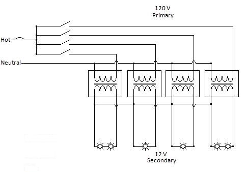
OK, I attached a diagram of the situation for review. The simple question is, "Can I use a common wire on the low voltage secondary side of the transformers as is shown in the drawing?" The transformers are 100 watts each and are all fed from the same 120V breaker; however, they are switched on and off separately. I know the neutrals can be common on the primary side but am a bit clueless as to what happens on the secondary side. In order to save wire and conduit sizing, I am wondering if I can run one side of my light cords directly to one side of the transformer secondary but connect the other side of my light to a common wire that is jumpered across all four secondaries. All the transformers are basically identical in ratings . I'm just not real sure about actual current flow in these secondaries in situations where all the lights aren't switched on at the same time and things like that.
485 x 338 - 19K

Comments

  • Mike GreenMike Green Posts: 23,101
    edited 2011-11-14 09:23
    Yes, you can use a common wire on the low voltage secondary side as shown in the drawing. I'm a little confused about what you're asking though. When the primary to a transformer isn't connected because the switch to it is open, there's nothing that flows in the secondary (or bulb). Do keep in mind that, in some cases, you have two bulbs in series. If they're 12V bulbs, they'll light somewhat less than 1/2 bright. If you want them to have normal light output, you'll have to wire them in parallel. Those bulbs will have to be rated at 50W or less to keep from overheating the transformer.
  • eiplannereiplanner Posts: 112
    edited 2011-11-14 10:37
    Thanks for replying Mike. Yes (laughing), I do see that I have shown the lights in series on my drawing. As they would have told me in Nuke school "That's a gross misconceptual error! (on my part)" lol Sorry, no, in real life I have them wired in parallel. Was really only trying to show that the transformers in my question would not be equally loaded. Didn't know if the load made any difference when it comes to the sharing of one leg among all the lights. So for ABC simplicity; Each light has a cord attached that has a black and a white wire coming out of it. If I run each light's black wire to one side of each secondary on the transformers and then I run all the whites from all the lights to a junction box and wire nut them all together with a single white wire that then daisy chains to the other side of each transformer secondary, am I O.K.? (Spelling it out for me, not you guys) My biggest concern was whether or not there is any type of phasing or polarities on these transformer secondaries. I understand that since I am using the same breaker (phase) to power up all the transformers that I have only one phase but I am not familiar enough with the wire coiling in the transformer to know if that made any difference at all when it comes to connecting the neutrals of my pool lights. So, just to clarify one last time. There are two wires coming off the secondary on the transformers. Does it make any difference at all which of these two I use for the hot and which one I use for the neutral? And, if I have 4 - 100watt transformers and lets say they are all 90% loaded and all switches are on, is there a possibility (because the neutrals are tied together) that this would arbitrarily overload and single transformer? Depending on wire lengths, splice resistances, or anything like that, could this result in one of the transformers carrying more of the load?

    I know I am excessively and probably stupidly making too much about this but I have basically got a miniature waterpark with over 75 pool, spa, waterfall, and landscape lights that I am connecting over a large physical area through many satellite j-boxes and transformer banks and I can ill afford to fry the components. For me it would greatly reduce the number of wires daisy chaining through some of these transformer banks of 4 to 8 transformers if I could do it with a single neutral.
  • stamptrolstamptrol Posts: 1,731
    edited 2011-11-14 12:37
    There shouldn't be a problem with using a common neutral on the low voltage side. That said, you could create a problem if the polarity (say X1) wasn't the same on each transformer as the points would be 180 deg out phase with each other and the voltages could add together instead of being at the same potential.

    Establishing the polarity of the transformers is a standard test and can be quickly done if the transformers aren't already marked. Just Google transformer polarity.

    Probably worthwhile grounding that neutral point in case one transformer fails winding to winding.

    Cheers,
Sign In or Register to comment.