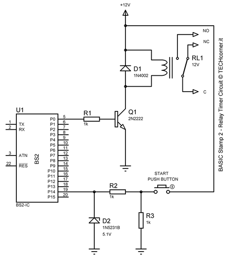
Relay Timer Circuit
Hi, I want to share this small project with community, looking forward to receive your feedback.
Here the 'Relay Timer Circuit' schematic:

Here the PBASIC code:
{$STAMP BS2}
=====================================================
Project name: Relay Timer Circuit
Author: Giuseppe Francesco Indelli
E-mail: giuseppe.indelli@alice.it
Website: www.techcorner.it
Started: 05 NOV 2011
Release: 1.0
=====================================================
Program Description
Relay Timer Circuit with the BASIC Stamp 2
Note that in this example the total activation time is 2 minutes
Minutes CON 1 activation time minutes
Seconds CON 60 activation time seconds
main:
PAUSE 10
IF IN14=1 THEN activate
LOW 0
GOTO main
activate:
HIGH 0
PAUSE (60000*Minutes)+(1000*Seconds) total activation time
GOTO main
Here the 'Relay Timer Circuit' schematic:

Here the PBASIC code:
{$STAMP BS2}
=====================================================
Project name: Relay Timer Circuit
Author: Giuseppe Francesco Indelli
E-mail: giuseppe.indelli@alice.it
Website: www.techcorner.it
Started: 05 NOV 2011
Release: 1.0
=====================================================
Program Description
Relay Timer Circuit with the BASIC Stamp 2
Note that in this example the total activation time is 2 minutes
Minutes CON 1 activation time minutes
Seconds CON 60 activation time seconds
main:
PAUSE 10
IF IN14=1 THEN activate
LOW 0
GOTO main
activate:
HIGH 0
PAUSE (60000*Minutes)+(1000*Seconds) total activation time
GOTO main

