

LTC1257 question
 damage31
Posts: 21
damage31
Posts: 21
I've picked up a couple of LTC1257's after reading Nuts&Volts #43, as this chip appears to be pretty much right up my alley for what I want to do.
I'm wondering if I can get a sanity check on implementing these DAC's - such as advice about any extra items that should be added to the circuit.
A little background:
I have a 29 gallon saltwater fish tank, and replaced the tanks stock lighting several months ago with twenty four 3 watt LEDs. I purchased 3 dimmable drivers as can be found here: Datasheet.pdf
Two of the drivers are 700ma, and the other is a 1050ma . Each of the 700ma drivers control a series of 8 blue leds, and the 1050ma driver controls a series of 8 white leds. At this time the dimming feature is implemented simply as three 50K pot's as shown in the datasheet to allow me the ability to mix the LEDs output to achieve a desired color temperature. At this time, I simply turn the drivers on and off via a timed switch, thus the leds are either on or off at their set brightness.
What I plan on doing:
I have a basic stamp 2 controlling an automatic freshwater top off to the tank. I have several lines free on the stamp, and I wish to expand the stamp to also have it control the dimming of the leds, so that not only can I control the leds overall color temperature via the stamp, but I also will be able to slowly ramp up and ramp down the leds overall intensity thus allowing a nice dawn to dusk effect. (instead of simply the on/off control I currently have implemented which startles the fish)
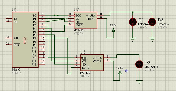
Each of the drivers accepts 0v-10v on an input line to control the drivers dimming. It appears that each driver has a Source current on the 0~10V input pin of 0ma minimum, with a 1ma maximum. Thus, I believe that by implementing 2 of the LTC1257 DAC's I should be able to control two of the led drivers with one dac, and the remaining led driver on the remaining dac. My plan is to have both of the blue LED drivers controlled by one dac, and the white driver controlled on another dac.
I might supply the dac's with 12.5v from an external source I am using to power a relay, so that I can get almost a full 0-10v output from the dacs but I have my concerns about voltage spikes, so I'm not 100% set on this just yet. I might be able to use the 10v output from the led drivers themselves, but I have to check my current voltage settings on the driver input to see how high i have each of the drivers set right now. I am currently planning on simply connecting the output of the dac to the dimming inputs on the LED driver, and tie the grounds of the circuit to the leds dimming circuit ground as shown on the datasheet.
I believe that this simple plan might just work. Am I missing anything?
I'm wondering if I can get a sanity check on implementing these DAC's - such as advice about any extra items that should be added to the circuit.
A little background:
I have a 29 gallon saltwater fish tank, and replaced the tanks stock lighting several months ago with twenty four 3 watt LEDs. I purchased 3 dimmable drivers as can be found here: Datasheet.pdf
Two of the drivers are 700ma, and the other is a 1050ma . Each of the 700ma drivers control a series of 8 blue leds, and the 1050ma driver controls a series of 8 white leds. At this time the dimming feature is implemented simply as three 50K pot's as shown in the datasheet to allow me the ability to mix the LEDs output to achieve a desired color temperature. At this time, I simply turn the drivers on and off via a timed switch, thus the leds are either on or off at their set brightness.
What I plan on doing:
I have a basic stamp 2 controlling an automatic freshwater top off to the tank. I have several lines free on the stamp, and I wish to expand the stamp to also have it control the dimming of the leds, so that not only can I control the leds overall color temperature via the stamp, but I also will be able to slowly ramp up and ramp down the leds overall intensity thus allowing a nice dawn to dusk effect. (instead of simply the on/off control I currently have implemented which startles the fish)
Each of the drivers accepts 0v-10v on an input line to control the drivers dimming. It appears that each driver has a Source current on the 0~10V input pin of 0ma minimum, with a 1ma maximum. Thus, I believe that by implementing 2 of the LTC1257 DAC's I should be able to control two of the led drivers with one dac, and the remaining led driver on the remaining dac. My plan is to have both of the blue LED drivers controlled by one dac, and the white driver controlled on another dac.
I might supply the dac's with 12.5v from an external source I am using to power a relay, so that I can get almost a full 0-10v output from the dacs but I have my concerns about voltage spikes, so I'm not 100% set on this just yet. I might be able to use the 10v output from the led drivers themselves, but I have to check my current voltage settings on the driver input to see how high i have each of the drivers set right now. I am currently planning on simply connecting the output of the dac to the dimming inputs on the LED driver, and tie the grounds of the circuit to the leds dimming circuit ground as shown on the datasheet.
I believe that this simple plan might just work. Am I missing anything?
707 x 364 - 57K
Comments
So I'm plodding ahead. Making some progress. I believe my hardware design is finalized, now I'm starting work on the software portion.
I'm going to use three LTC1257's daisy chained together (one per LED driver) to (hopefully) keep things simple.
Right now I'm trying to teach myself how to ramp the LTC1257's up/down over some period of time, trying to keep things as simple as possible for now.
I will be using a DS1302 as a time keeping chip, and now just need to figure out how best to apply it in my design.
I am guessing that I will probably use the DS1302 to simply trigger the stamps ramp up/down loop, and just do some sort of timed pause statement within the loop code to control how long the ramp will take.
I would like to come up with a more elegant solution, but don't know how at the moment.
I'd like to be able to simply change the ramp time (specified in whole minutes) and let the stamp do some math to hammer out how many steps per second it needs to go. But I am not sure how to do that just yet. I suppose the loop delay value will simply need to be some calculated number.
After I get the ramp figured out, my next step is to figure out how to apply a % to the output, so that I can control the final ramp value. For example, If only want 80% of the LTC1257 available output, I would stop at about step # 3276.
I had written a whole bunch o'words in response, but then realized you've probably already figured things out.
Could you post your code? It might give us a better idea where the difficulties are residing.
My problem is, how can I take a variable numeric value that is expressed as a percent in the range of 1% - 100%, (so, say 80%) and use it to get the %'s numeric value of 4096?
It looks like the answer to my question is in front of me, but I dont know how I can vary the fractional number in code that needs to be multiplied by 65536 to get the result that needs to be used. I'm stumped. (and tired which isnt helping at the moment)
eg: If i want 80% of 4096, I would expect the calculation to return something near a value of 3276.
What the example looks like to me is I would take .8 * 65536 to get 52428 , and then take 4096 ** 52428 to get 3276.
The problem is, I cant do the first part in the stamp (.8 * 65536 to get 52428) as far as i can tell...What am I missing?
http://www.emesystems.com/BS2index.htm#math
But I think I'll attack this from a slightly different angle. I think what I'll do is just increment the numerator up/down, and show the value as a % on the LCD. It seems like that will be a lot easier given my limited capabilities.
Side note: I started to use a % calculation found here which was fairly good and meets probably most peoples needs, but found I wanted this instead. Showing the % values as a whole % wasn't quite granular enough for my tastes. Mr. Allen saves the day again.
My efforts with the BS2 have not required any serious math computations...yet. And I'm a tad surprised that the Forum experts haven't already chimed in on this thread. Usually members are coming out-of-the-woodwork with valid and interesting suggestions on a project like this.
Happy Thanksgiving to you!
After this project is done, I might just have to whip something up...
...ha! LAAAY-ZEEE!!!
Actually - I used to have a whole slew of pre-defined code chunks tucked away as Visual Studio macros that would allow me to pull down a menu, select a code block, affirm, and the code block text would be inserted into the opened function where the cursor was located.
I don't think the PBASIC IDE has any sort of ability to do the same.
The circuit is breadboarded, and in the next couple of days ill be soldering it up.
I'll be posting my code + a circuit + a video of this in action in a few days once I'm 100% sure that everything is completely solid.
But I cant take credit for much of what I am doing.
I used the search feature here on the forum dozens (hundreds) of times, and was able to get all my issues/questions figured out.
All I can say is thanks to everyone for all of the sample code, because without it, my project would not be functional.
I copied/pasted many lines of code from the forum discussions to piece together what I needed.
Dr. Tracy Allen is a math god. I'd be in a bind if he did not share his knowledge.
Mr. Chris Savage and all his work/demos about the ds1302 also saved me several headaches.
Mr. Mike Green also had many helpful posts.
Whats neat is that after much work shrinking my code down to the bare minimum, It appears I'm only using about 70%-75% of the available program space. And I still have 3 pins left over, without even trying to save pins.
I suspect that if i think on it a bit more, I can probably save another two pins just by sharing some lines between the ds1302 and the ltc1257.
Or I could implement something like a 74HC595/74HC165 to expand my outputs/inputs a little. I've got 5 lines that are outputs that would work nicely on a 74HC595...
with the extra open lines & code space I'm debating on adding a serial LCD or ds1620/lm34 or 2 or 3 buttons.
Isn't it amazing what can be done with these little bits of technology?