Fried BASIC Stamp 2, Bad Inverter?
Hey everyone,
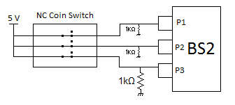
Unfortunately, I fried a BS2 while connecting a circuit to test whether or not my coin counter worked... Here's a simple schematic of my circuit when the BS2 stopped functioning:

I have a set of three coin switches (nickels, dimes, quarters). Each switch can be operated in normally open or normally closed configurations. I chose to use my switches in the normally closed configuration. Each switch was connected to 5 V on one end, then connected to pins 1, 2 and 3 respectfully. Each pin had a 1 kΩ resistor attached to ground. This configuration seemed to work for a bit, but then my BS2 simply stopped being recognized by the Parallax software. Also, the BS2 was extremely hot to the touch... Did I fry the regulator on the BS2?
I realize I should have connected the resistors in series with the pins, rather than in parallel to them. Would this modification prevent this mistake from happening again? Is my BS2 repairable? Any help is greatly appreciated!
Thanks,
Gavin
Unfortunately, I fried a BS2 while connecting a circuit to test whether or not my coin counter worked... Here's a simple schematic of my circuit when the BS2 stopped functioning:

I have a set of three coin switches (nickels, dimes, quarters). Each switch can be operated in normally open or normally closed configurations. I chose to use my switches in the normally closed configuration. Each switch was connected to 5 V on one end, then connected to pins 1, 2 and 3 respectfully. Each pin had a 1 kΩ resistor attached to ground. This configuration seemed to work for a bit, but then my BS2 simply stopped being recognized by the Parallax software. Also, the BS2 was extremely hot to the touch... Did I fry the regulator on the BS2?
I realize I should have connected the resistors in series with the pins, rather than in parallel to them. Would this modification prevent this mistake from happening again? Is my BS2 repairable? Any help is greatly appreciated!
Thanks,
Gavin


Comments
Both the "What's a Microcontroller?" tutorial and the "Basic Stamp Syntax and Reference Manual" show how to connect switches to a Stamp. Both of these are included in the Stamp Editor's help files. The only difference from what you've shown is a 220 Ohm resistor between the Stamp I/O pin and the junction of the 1K resistor and the switch.